Robot
by
Duane Gustavus
June 15, 2003 -- dlg
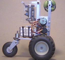
n01.jpg - This picture shows the robot's main frame. The two shafts which
project from either side of the lower frame are the drive wheel axles. The
wheels mount on the projecting shafts, and on the other end are the pulleys
which connect by belts to the motors mounted higher up. Just below the
motors, the pulleys mounted on the optical encoders are visible. This was
an experiment since these encoders are tied directly to the wheel movement,
and only indirectly to the motors (ie through the gearbox). This is ideal
for odometery, but it was not clear how well it would work for motor control.
So far, there has been no problem running the PID speed controller from this
sensor setup. There are 597 encoder ticks per wheel revolution or just over
41 per inch. The other devices visible as a black rectangle just under the
motors are Sharp IR ranging sensors. The motors are surplus Pittman 19.2v DC
items with attached gearbox (I'm not sure about the gear ratio).
n02.jpg - These are the components which are assembled to make the caster
wheel. The large shaft on the caster assembly fits though the big hole in
the end of the right angle frame and is held my a set screw. Another IR
ranging sensor is mounted dead center on the frame.
n03.jpg - Here are the two pieces from the n02.jpg photo put together and shown
from the top side. The four holes are used to mount the battery and DC-DC
converter, while the slots are used to bolt the whole thing to the main frame.
n04.jpg - This is the battery assembly comprised of three 6-cell 1800mah NiMH
AA packs clamped between polycarbonate end-plates. Due to the angle of the
picture, you can only see two of the four bolts which fit the the holes
mentioned in the n03.jpg picture description.
n05.jpg - This shows the battery and caster assembly bolted to the main frame.
The bot is lying "face down" in this picture, and still has no drive wheels.
n06.jpg - This is the complete bot mechanical assembly shown upright with
drive wheels mounted from a rear, three-quarter angle view. The metal plate
on top of the batteries is where the DC-DC power converter mounts (which I
am working on at this point). The green omniwheel mounted in the top/front
of the frame is because I expect to be falling down a lot when I try to go
into balancing mode. It is very rugged, and will actually allow the bot to
maneuver reasonably well when it is flat on it's face (which will probably
be much of the time in the early going 8)
n07.jpg - This picture shows the motor controller board with four input buttons
on the bottom. The board is mounted to a 1/4 inch thick aluminum plate visible
between the motor controller and input buttons. The MRM332 cpu board mounts
on the other side of this plate. The sides are made from acrylic pieces that
are fastened via bolts screwed into the sides of the same aluminum plate. One
of the aluminum spacer tubes is shown at top. These tubes have a piece of
10x32 allthread through them which is clamped on each end to make a hopefully
crash-resistant case.
n08.jpg - Here is the view from the other side showing the MRM332 board. The
case is mounted to the frame with the cpu board on the inside. Just visible
at the top are the holes which 10x32 allthread passes through on it's way
through the back frame members. At the bottom is a slot instead of a hole
so the case can be swiveled up and out of the way while still being attached
to the frame. Yes, the cpu reset switch is quite hard to reach with this
arrangement.
n09.jpg - This shows the cpu case mounted to the bot frame with a ruler at the
base for scale. The length is about 10 inches; the wheelbase a little less
and the height a little more. The wheels were contributed from a model R/C
truck, and chosen for their suspension rather than for odometry accuracy.
The caster wheel was an R/C model airplane accessory, and is also air-filled.
This is the first bot I have made that doesn't "clunk around" on hard surfaces
and has at least minimal suspension for running over objects or out of doors.
The shaft projecting up out of the caster assembly mounts a gear to allow
tracking the position of the caster wheel (which I currently do not do, but
it has been useful in previous three-wheeled bots).
n10.jpg - A side view of the largely complete bot (still missing power circuit
and some sensors). In balancing mode, the bot will have the caster wheel off
the surface because the balance point involves shifting the battery weight up
and over the drive wheels (ie tilting forward ~20 degrees). This postion
places the omniwheel well in front of the frame, and hopefully at the point of
first contact most of the time. In other words, standing "still" will have
the bot frame tilted at about a 20 degree angle (rather like a T-rex 8) If it
falls either forward or backward, the bot should still be able to maneuver
even if it cannot get back into balancing mode (or so goes the enchantment).
LMD18200pcb.jpg - this is a picture of the LMD18200 motor controller pc board.
LMD18200-built.jpg - this is the motor controller board after construction.
Update: 04 April 04 - dpa
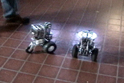
Robot acquires, follows, and matches the speed of another robot. In this case, dpa's robot, nBot, is navigating around a 5 foot square, and Robot is following.
Here are a couple of videos of the behavior in Duane's kitchen.
low res mpeg (3.2Mb)
hi res mpeg (16 Mb)
The robot is using two Sharp infrared proximity detectors to find the edges of the robot
and lock on to its trajectory. nBot manages to lose it twice by "scraping it off" on
nearby bright, hard, reflective surfaces.
Back to dpa's robots