for the
Pittman GM8712 Gearhead Motor
Pittman
GM8712-31 19.1 V. DC Gearhead Motor
http://www.pittmannet.com/122100.html
Pittman
GM8712-31 19.1 V. DC Gearhead Motor
http://www.pittmannet.com/122100.html
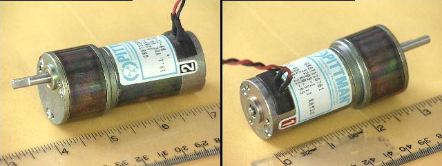
Some nice small DC gearhead motors recently appeared on the electronic surplus market, suitable for jack-rabbit size hobby robots of 5 or 10 pounds. These motors are manufactured by Pittman, model number GM8712. BGMicro and Tanners, two surplus houses in Dallas, stocked a few gross of these and sold them for $10.95 apiece. They were snatched up quickly by the membership of the Dallas Personal Robotics Group, though I believe a few are still available. Apogee appears to sell the same motor for $15. Check out: http://www.apogeeinc.com/mfg.html EricYundt of the DPRG reports that Automation Solutions has these gearmotors (new?) listed for a cool $73.90 a pop.
Surplus DC gearhead motors suitable for hobby robots are very much "Targets of Opportunity." It is difficult to find the desired combination of characteristics: voltage, stall current, gear ratio, size, encoder resolution , noise levels, and of course cost. These particular Pittman motors are ideal in many ways for our purposes but lack shaft encoders. This article describes a simple method for constructing home-brew encoders for these nifty little motors. It arose from a series of email postings on the Dallas Personal Robotics Group (DPRG) list server and The Seattle Robotics Society (SRS) list server, and quotes freely from those postings. Many thanks to all the conglomerated brain power that went into this simple modification.
I. The Motors
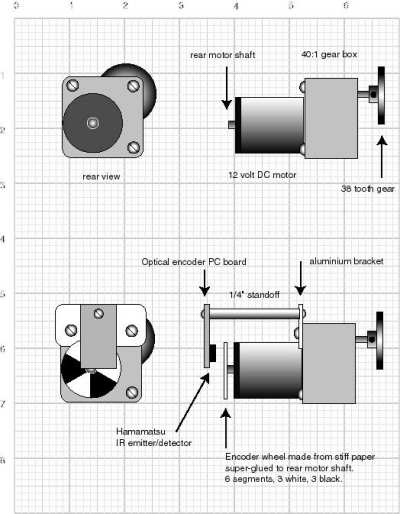
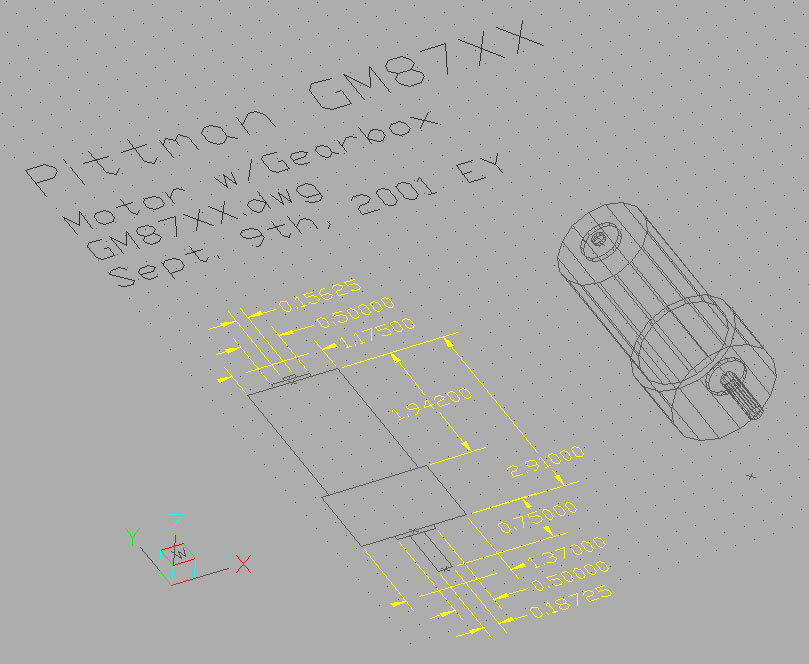
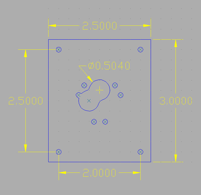
Eric provided us with a synopsis of the motor's specifications, along with CAD drawings and dimensions of the motor itself and dimensions for a motor mount (both available in .dwg and .dxf formats).
Eric's synopsis:
The spec sheet says of the 19.1V GM8712 gearmotor, with a 60.5:1 reducing gearbox:
Gearmotor Data:
Gearbox Efficiency 66%Motor Data:
No-load Speed 128 RPM
Continuous Torque (Max) 1.3 oz-inWinding Data:
Peak Torque (Stall) 5.1 oz-in
No-load Speed 7729 RPM
Torque Constant 3.06 oz-in/AEric continues: I take all that to mean (in theory) out the gearbox shaft:
Resistance 10.80 Ohms
No-load Current 0.14 A
Peak Current (Stall) 1.76 A
Continuous Torque (Max) 1.3 oz-in * 60.5:1 * 66% = 51.9 oz-inAlan Bredon reports that Pittman specs two basic gearbox torque ratings: 500 oz-in for the larger type, and 200 oz-in for the smaller. The latter is in good agreement with Eric's calculations. These motors seem to work nicely at 12V running about 70 RPM with a stall current around 1A . That is low enough to use common H-bridge driver chips like the L293 used by the Handy Board, EyeRobot controller, MicroCorp controller, M.I.T. 6.270 board, and similar small to mid-sized robot controller boards.
Peak Torque (Stall) 5.1 oz-in * 60.5:1 * 66% = 203.6 oz-in
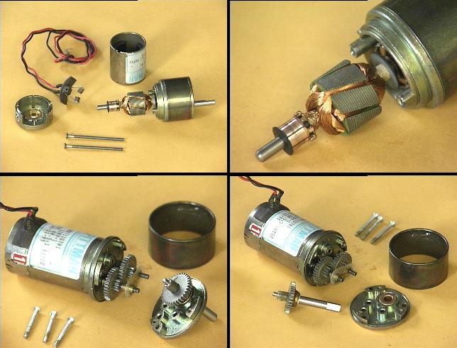
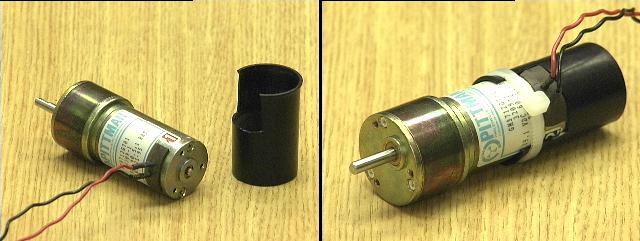
Pittman GM8712 disassembly of motor and gearhead
I took two of the Pittman GM8712 motors out to the lake-side retreat of Michael Hamilton, aircraft engineer and designer extraordinare for Traxxus (toy cars) et al. We took one apart and played with it. He pronounced it "first rate stuff."
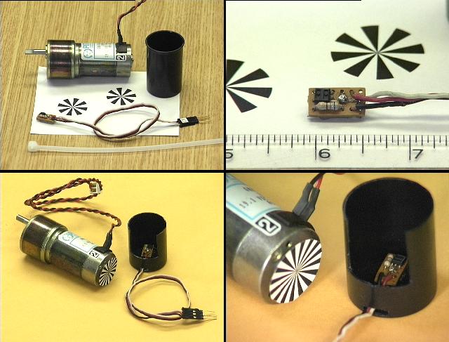
It is a seven pole motor, which accounts for the high torque at low rpm and for it's extremely quiet operation, always a plus for domestic robots. Notice in the upper right-hand image that the seven poles are wound with lots of extremely fine wire (we measured 12 ohms). The poles are also "skewed" helically. Michael tells me this provides for smoother operation, as the poles "overlap" each other.
The gearhead has 4 stages. We counted the teeth and the last three stages have 32 tooth spur gears driven by 10 tooth pinions, 3.2:1 per stage. The first stage has slightly smaller teeth and we were not able to count them. However, they must provide about 1.8:1 ratio for a final ratio of 60:1. All gears are "high quality" metal gears with steel axles riding in bronze bushings.
Michael was of the opinion that we should probably not mount wheels directly on the output shaft because of the small diameter of the rear pin and bushing, as shown in the lower right hand picture above. I said we were thinking of a 5 to 10 pound platform. He suggest that someone suitably motivated could probably press out the bronze bearings and replace them with ball bearings.
David Peterson dug through the Pittman web site and reported similar findings. He quotes:
"Sleeve bearings are really not capable of supporting large radial loads, and virtually no axial load. The actual radial load capability depends on a number of factors, but is typically on the order of a couple of pounds."
"We do offer ball bearings as an option on the output
in place of the sleeve bearing. This greatly increases the load capability.
Again, the exact values depend on a number of factors and are somewhat
subjective. For our standard ball bearing for this unit type, we
would typically recommend less than about 8 lbs radial load and less than
about 2 lbs axial load."
II. Home-brew Encoders
We have had good success in the past with home-made encoders using paper wheels printed on a laser printer and sensed with the Hamamatsu P5587 IR emitter/detector. My last two robots have used this system with the encoder wheels simply super-glued to the motor shaft. The paper disks are very light and require no careful balancing to prevent vibration at high rpm. The super-glue is much stronger than the paper itself and so provides a robust means of attachment.
A. The SensorThe Hamamatsu parts have proven very reliable and easy to use. We have ordered them in the past directly from Hamamatsu but they are also available from Zargos Robotics and Acroname, whose web page includes a simple schematic:
http://www.acroname.com/robotics/parts/R64-P5587.html
Hamamatsu typical connections from Acroname
B. MountingMy SR04 robot uses a similar method. On those motors the Hamamatsu sensor is mounted on a small piece of perf-board which is attached to an aluminum tube, itself attached to an aluminum bracket screwed to the motor casing. These have worked reliably for about 4 years now, and my initial reservations about using paper disks have been assuaged. Disadvantages of this implementation are that it is not light-tight and the paper disk is exposed to the clumsy hands of this robot builder.
SR04's encoder disk implementation.
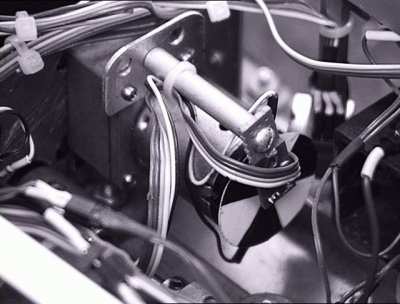
Left Encoder disk and sensor on SR04
Some improvements we wanted to make to this design for the Pittman GM8712 motors were:
1. A more easily adjustable mount for setting the sensor-to-disk distance,As we discussed the design options, Jeff Birt made the happy discovery that a common black plastic film canister fits perfectly over the case of the Pittman motors, with a small cutout for the power connections. These can be held snugly in place with a plastic cable tie. Mounting the Hamamatsu perf-board in the back of the canister allows the spacing between the sensor and the encoder disk to be adjusted simply by sliding the film can in and out.
2. A light shield and protective cover for the paper disk and sensor,
3. The ability to experiment with quadrature signals,
4. A simpler method of attachment.
I am planning to run these motors off 12 NMH cells, which works out to about 15 volts fully charged. Working backward, the gearhead is spec'd at 128 rpm at 19.1 volts and we measure about 70 rpm at 12 volts. That's something like 6 rpm per volt, if the response is linear. So,
C. Encoder segments
15 volts * 6 rpm/volt = 90 rpmThe gearhead has about a 60:1 ratio, so the motor speed at 15 volts would be:
90 rpm * 60 = 5400 rpm motor speedOr to put it another way:
5400 rpm / 60 seconds/minute = 90 revolutions per second.My last generation of robots had a read-sensor-write-output cycle time of 10 hz, or 100 milsec. That means the sample time for the encoders is 100 milliseconds. For the current generation of autonomous platforms I increased the rate to 20 hz, which is only a 50 ms sampling window. For the new mobile platform I'd like to increase that again to 30 or 40 or perhaps even 50 hz, with correspondingly shorter sample windows. A 50 hz update rate means that if the robot is to measure motor velocities by counting how many encoder ticks occurred in the previous sampling interval, we only have 20 milliseconds to collect counts.
This number is needed to know how many encoder ticks are required for smooth speed control, which in turn depends on the sampling technique and the particular method of motor control. The SR04 robot returns 1000 ticks per second per wheel at full speed. Since it's update rate is 20 hz, that means
1000 ticks / 20 hz sample rate = 50 ticks per sample at full speedSlow speed is arbitrarily defined as full speed / 10, so
50 ticks per sample full speed / 10 = 5 ticks per sample, slow speed.For the speed control technique I am using, 5 ticks is close to a minimum number required for smooth speed control. To have this same granularity and resolution on the new platform with a 50 Hz sample rate will require :
50 ticks/sample * 50 samples/second = 2500 ticks per second, full speed.So we need paper encoder wheels printed with 28 black and white divisions. Empirical testing with the actual device determined that 20 segments on a one inch encoder disk is about the largest number that can be read robustly without the need for precise sensor placement and alignment. Further experimentation with a two-sensor quadrature implementation suggests that 15 black and white segments might be more appropriate.
2500 ticks per sec / 90 revs per second = 27.78 ~ 28 ticks per revolution
D. Making the DisksWe printed the encoder disks using a simple postscript utility which I believe began it's life as a posting on the SRS list server. I do not know the original author. We are currently using fairly thick matte-finish photo quality paper for the disks. It is thick enough not to need any other backing to stay stiff, and does not tend to absorb water over time and so resists warping.

%! Postscript utility for printing an encoder wheel
%
/inch {72 mul} def % #points/inch (don't change me)
/size 0.5 inch def % radius of encoder wheel
/segments 16 def % number of segments (black and white)
/angle 360 segments div def/wedge
{ /radius exch def
/angle_s exch def
/angle_e exch def
newpath 0 0 moveto
0 0 radius angle_s angle_e arc
closepath
} defgsave
1.0 inch 1.0 inch translate
0 1 segments {
360 segments div rotate
angle 0 size wedge
2 mod 0 eq {1} {0} ifelse
setgray fill
} for
grestoreshowpage
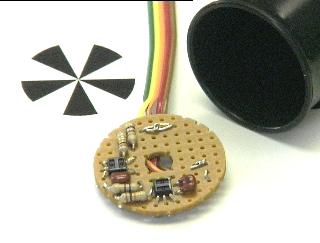
III. Construction:
The materials for the completed shaft encoder consists of the paper encoder wheel, Hamamatsu emitter/detector, black plastic film canister, and a cable tie. The wheel is super-glued to the rear of the motor shaft. The Hamamatsu is mounted on a small piece of perfboard with a couple of other components. The perfboard is glued into the back of the film canister with the leads exiting through a slot in the side. The canister was cut down with an xacto knife and slotted to clear the motor wires.
The cable tie allows the film canister to slide in and out to adjust the exact distance for the Hamamatsu sensor. Then it is tightened to hold it in place. This home-brew encoder requires no machining and can be assembled with simple hand tools. It represents an improvement over our previous encoders in that it is adjustable and also has a light shield and protective cover over the encoder wheel.
IV. Testing
We powered the motor from a DC bench supply and connected the encoder to an O'scope to adjust the sensor spacing. Once we were happy with the square wave thus generated we tightened the cable tie to hold the film canister snugly in place.
Next we dusted off an M.I.T. 6.270 robot controller board and wrote a simple piece of code to read the encoder using the TIC3 interrupt of the HC11 processor, printing the accumulated counts on the controller's LCD once per second.
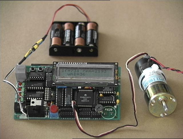
Home-brew encoder connected to an 68HC11 Timer-Input Compare
port
on the M.I.T.
6.270 Robot Controller board, similar to the "Handy
Board."
The test setup is shown above. The motor is powered from a DC bench supply not pictured. The LCD indicates that the encoder is currently generating 731 counts per second, with a motor speed of 2193 RPM and a final output shaft speed of 36 RPM. Here is what we measured:
Pittman GM8712 with 20 segment encoder.
No-load measurements
| Voltage (V) | Current (A) | Ticks per/sec | Motor RPM | Gearhead RPM |
| 19.1 | 1.4 | 2641 | 7941 | 132 |
| 15.0 | 1.4 | 2050 | 6156 | 102 |
| 12.5 | 1.3 | 1658 | 4980 | 82 |
| 10.0 | 1.2 | 1302 | 3906 | 65 |
| 7.5 | 1.15 | 936 | 2908 | 46 |
| 5.0 | 1.0 | 570 | 1710 | 28 |
| 4.0 | 1.0 | 434 | 1302 | 21 |
| 3.0 | 0.9 | 288 | 864 | 14 |
| 2.0 | 0.8 | 156 | 468 | 7 |
| 1.5 | 0.75 | 84 | 252 | 4 |
| 1.2 | 0.75 | 37 | 111 | 1 |
| 1.1 | 0.75 | 0 | 0 | 0 |
V. Quadrature Encoding:
These encoders are read very robustly by the Hamamatsu P5587 IR emitter/detector unit sold by Acroname and Zargos as previously discussed. A single unit can be used to count encoder divisions for velocity information. That's all the SR04 robot has. Two are required in order to read both velocity and direction. This is what I'm hoping to implement for the new platform.
Quadrature encoder is actually pretty simple in this case. The two Hamamatsu's are mounted such that when one is "seeing" the edge between a black and white segment, the other is centered in a segment. The HC11 and similar processor have builtin hardware for detecting edges and generating interrupts. The 68332 can do all of this in hardware with "TPU" channels.
After a vigorous exchange of email it was determined that two sensors mounted at right angles to each other will produce quadrature signals for an ODD number of encoder white or black segments. We turned a couple of pieces of perf-board a little smaller than the diameter of the back of a film canister, about 1.15 inches.
Then we used the arrangement of the perf-board holes to get the two sensors oriented at right angles. By making the disk fit snugly in the film canister to which it is glued or screwed, the concentric alignment of the sensors with the motor and encoder disk is guaranteed. For test purposes we printed 22 segment (11 black and 11 white), 14 segment, and 10 segment encoder disks. The 14 and 10 segment disks seemed to give the best performance in terms of ease of alignment of the two out-of-phase signals.
Twin sensors mounted at 90 degrees,
a film canister and an odd numbered encoder disk.
Using a dual-trace scope we aligned and calibrated the two signals in the same manner as the single channel implementation. The encoder software is only slightly more complex than for the single channel case. Each time the A channel generates a interrupt the B channel is sampled. For positive going edges ( black to white transitions) the B channel will be centered on a black segment when the motor is turning in one direction, and a white segment when it is turning in the reverse direction. Negative going edges are just the opposite. Thus the motor velocity and direction can be determined.
Kipton Moravec of the DPRG suggests that this is best detected with a simple state machine. He further reports, "A good one that has already been reduced can be found on the Xilinx web site. I have it implemented in a macro in my Xilinx SW. The write-up can be found at: http://www.xilinx.com/xapp/xapp012.pdf"
Robert Singleton proposes that a simple quadrature scheme can be implemented using two sensors mounted in a line, by printing a 90 degree phase shift pattern on the encoder disk itself. He has samples of this encoder disk and several others including binary and graycode patterns at: http://www.linuxlegend.com/~slugmusk/encpix

Robert's quadrature pattern
Kipton has volunteered to design a simple PC board that can be used as a single or quadrature mounting for one or two Hamamatsu's, sized to fit in a film canister. The PC board layout and gerber files can be found here. Robert is evaluating a Hewlett-Packard HEDR-8000. He describes it as a "surface mounted 8 pin (S08 package) device with all optics and electronics to read, reflectively, a 75 or 150 line-per-inch pattern and provide a quadrature output." He directs the interested reader to go to the Hewlett-Packard web page and look under "Motion Control." Dan Creagan was also inspired to mount home-brew encoders on his Pittman motors. His work can be found at: http://academic1.bellevue.edu/robots/tanner
We have in the past built custom gear trains and shaft encoders for our hobby robot motors. Home-brew gear trains are difficult to fabricate and suitable gears from suppliers like Berg or SmallParts are generally quite expensive. In our experience it is much easier to find a motor with the appropriate electrical and mechnical characteristics and add encoders. This design is by far the best combination of simplicity and mechanical ruggedness to date. Thanks again to the many DPRG and SRS list members who contributed data and brain power to this on-going effort.
Dallas, Tx
11 Sept 01
dpa