nBot Robot Platform Exploded Views
nBot Robot Platform Exploded Views
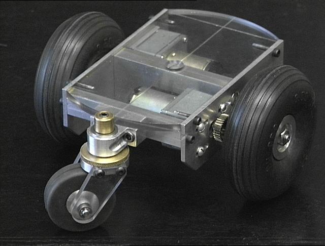
These robots were created in my home machine shop. These are the platform trucks (chassis and motors) which eventually became the two-wheeled balancing robot "nBot," along with an auxiliary castering tail wheel. The third wheel was used for a three-wheeled version of the robot.
All three of the wheels use rubber tires removed from standard model airplane wheels, fitted to custom aluminium hubs turned on my Enco-Maier 8" lathe. The motors are 12 Volt D.C. gearhead motors, with a gear reduction of 40:1. A final output stage consisting of a pinion and spur gear attached to the motor(s) and axle shaft(s) give an additional 2:1 reduction for a total gear reduction of 80:1.
Click on the images for larger versions of the pictures.
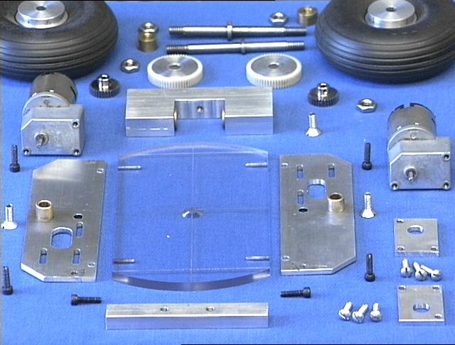
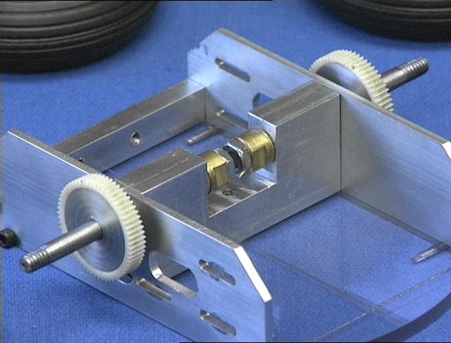
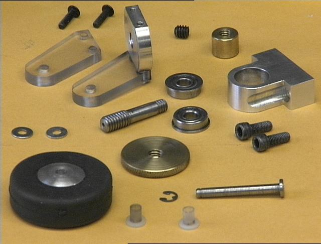
The platform is constructed using an aluminium axle mount and two aluminium
side beams, attached to a 1/4" clear Lexan upper deck. The
above image includes all the parts of the basic two-wheel truck.
In the foreground can be seen the 1/4" Lexan deck between the two
aluminium side beams, with 3/8" bronze bearings already inserted in the
beams. Behind that is the aluminium axle block (with bronze bearings
inserted in the inner surfaces) flanked on either side by two 12
volt D.C. gearhead motors. In the rear of the image are the axles,
gears, and main wheels.
The axle mounting block was squared up on the lathe using cylindrical squares and a face plate.
Then the axle hole was bored in a single operation without removing the block from the lathe,
insuring that both axles are aligned with each other and square with the mounting surfaces
of the block. The the block was removed from the lathe and the inner section between the two
axles was removed with the vertical mill. The aluminium wheel hubs and steel axles were
also made with the lathe. All the other structural components were machined from aluminuim
and Lexan stock using the mill. I also use the mill, along with the
"poor man's dro" and center and
edge finders, for laying out the parts, and as a drill press.
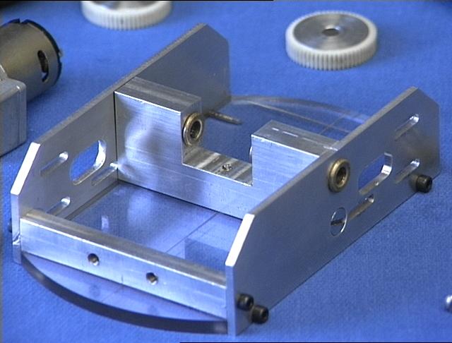
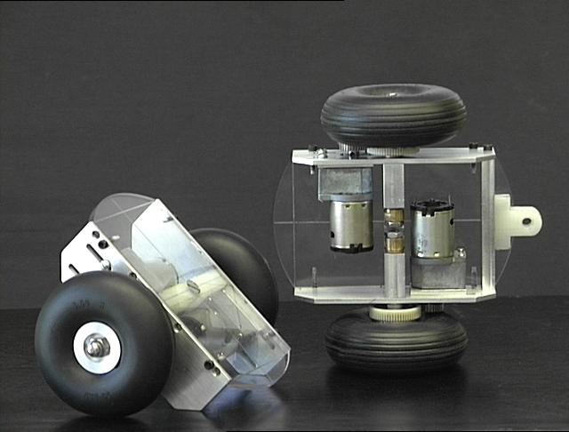
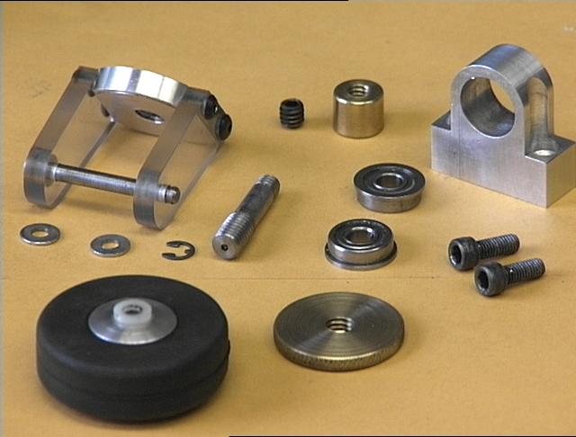
Here is the main structural unit assembled, upside down; clear
Lexan deck next to the table, the side beams and axle block attached,
and all four bronze bushings inserted into the block and beams. The
aluminium beam across the near (rear) end in the image above is the attachment
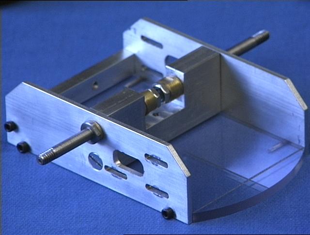
point for the tail wheel caster. The center image shows how
the axles are captured between a machined shoulder on the outer ends and
a threaded stop and lock nut on the inner ends. The 80
tooth spur gear is a standard delrin replacement gear for electric R/C
race car transmissions. A pair of turned aluminium pressure plates
centers the gear on the shaft, and sandwiches the gear between the
axle shoulder and the wheel, all held with lock-nuts on the end of
the axles.
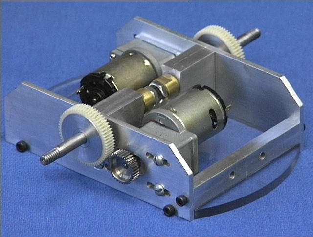
The motors are mounted to the side beams on milled slots for the three
mounting screws and the gearhead output shaft. This allows the motor/axle
spacing to be adjusted for different sized spur and pinion gears.
The gears need to be set to mesh as closely as possible without binding.
One easy way to set this spacing is to place a piece of wrapping paper
between the gears, mesh them as
tightly as possible and tighten the mounting screws, and then removed
the paper by manually rotating the gears.
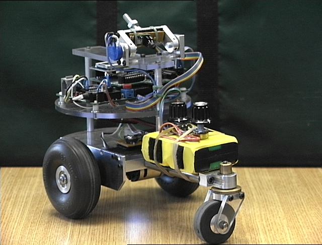
For the two-wheel balancing robot the weight distribution is centered
over the axles, with the battery pack, which is the heaviest component,
attached directly above the center line. For the three wheel
version, the batteries were moved as far back toward the tail wheel
as possible, and the center of gravity was then located an inch or so behind
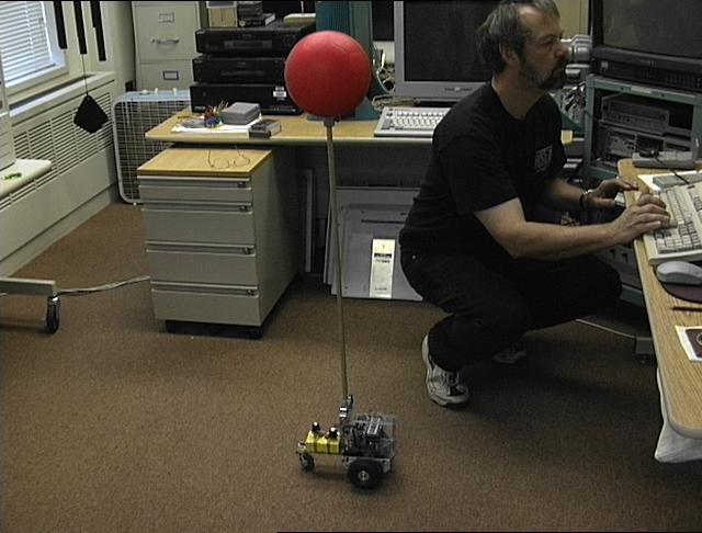
the main axles for stability. For the three-wheeled inverted
pendulum
pole-balancing configuration, the tail wheel was extended still
further behind the main wheels with the addition of 3 inch steel rods
as spacers, and the
batteries mounted on those spacers.
Tailwheel and ballbearing caster
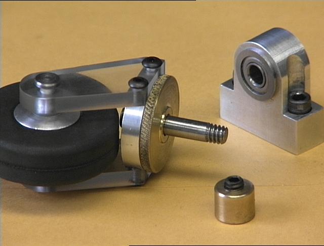
Two 1/4" Lexan struts attached to a threaded aluminium bearing block
form the yoke for the tailwheel axle. The axle is held in place with
spring clips. The aluminum wheel has teflon bearings for this axle
inserted in either side of the hub. A short vertical axle threads
into the bearing block and is locked in place with a knurled brass lockplate.
The lockplate has a slight shoulder in the center to bear against the inner
race of the ball bearing in the caster support. The support has
two cap screws for attachment to the caster beam on the platform.
It has upper and lower ball bearings for the vertical axle, which is captured
with a brass adjustable locking nut -- a tall brass nut with an allen-head
setscrew inserted in one end.
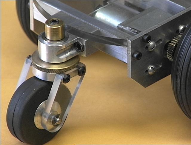
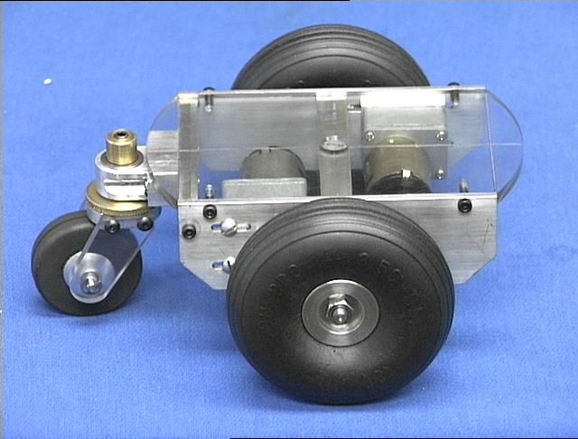
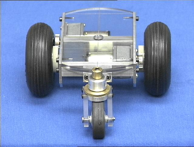
Here is the assembled and installed tail wheel for the three-wheel configuration. The caster attachment beam is fastened to the side beams with a 6-32 cap screw in either end and a counter-sunk flat head screw (not shown) vertically through the Lexan. With the gears removed from the motor shafts so that the wheels can spin freely, the robot platform at this stage of construction is a lot of fun to vroom-vroom around on the floor by hand.
Next step in development was to add the batteries, regulator, microprocessor,
and h-bridge, and build shaft encoders for the motors. With those
elements in place the motor Pulse Width Modulation (PWM) code and
Proportional Integral Derivative (PID) speed controller were developed.
nBot two-wheel balancing robot
My home machine shop
My robots homepage
04 January 2003
dpa