--------------------------------------------------------------
Improving Servo Positioning Accuracy
David P. Anderson
Howdy SRS,
I have documented a technique for improving the accuracy and repeatability of servo positioning by use of an external reference potentiometer.
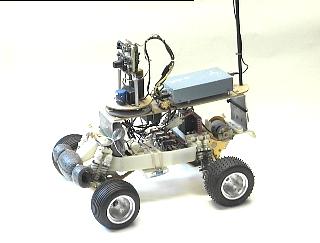
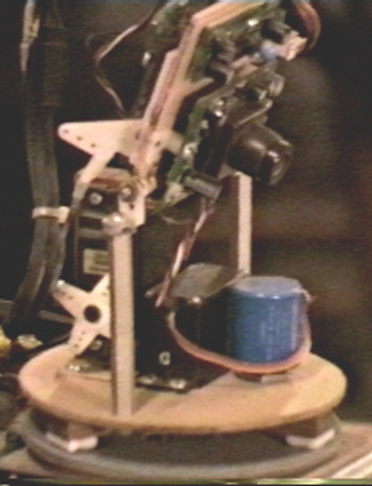
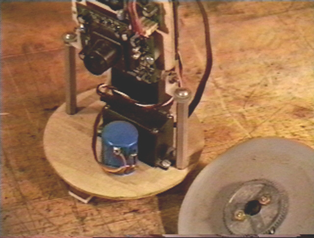
This problem originated when we were developing a two-axis head for a video camera mounted on our remotely piloted vehicle. We wanted a vertical movement of 110 degrees, so the camera can look straight up, straight ahead, and down forward about 20 degrees. This is doable with a standard R/C servo. We also wanted a horizontal rotation axis of just over 360 degrees, so the head can rotate around left or right and see straight behind itself.
We looked at R/C sailboat wench servos for the horizontal rotation, but they are pretty pricy. Besides, we have lots of standard Futaba and Airtonics servos from our other hobby, R/C airplanes, laying around.
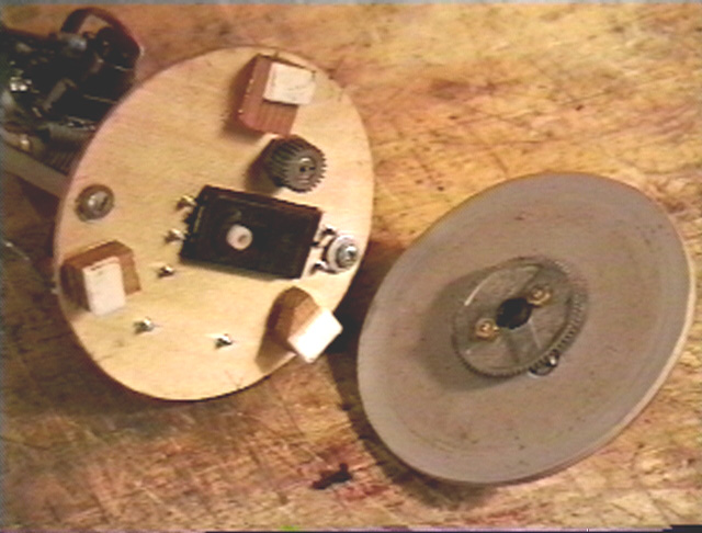
The first instantiation was to gear up a standard servo 1:3 by putting a large spur gear directly on the servo output wheel, 36 teeth, and a small gear attached to the base of the camera platform vertical axis, 12 teeth. This worked fine to give us a bit more than 360 degrees of rotation with a standard servo.
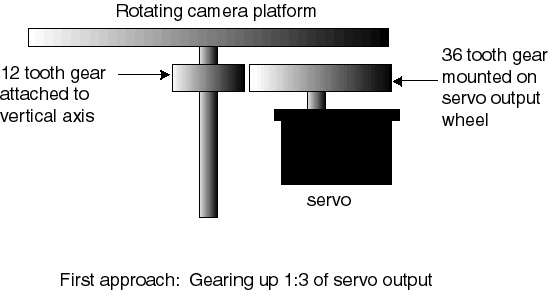
The problem with this approach is that when the angular movement of the servo is geared up x3, the positioning error is geared up x3 as well. This means that the head/camera does not return to the same position when the R/C transmitter sticks are centered, depending on which direction it is turning and how far. The whole thing was workable but sloppy.
The solution to this problem was to use an external pot to generate the feedback for the servo positioning electronics. This same technique should work with any servo driven scheme to increase the positioning accuracy.
A little mini theory-of-ops might be useful here. I refer the interested reader to the excellent overview by Lee Buse in the September 2000 SRS Encoder:
http://www.seattlerobotics.org/encoder/200009/S3003C.html
The position of the output wheel in a standard R/C style servo is dependent on two pulse streams, one of which is the external control signal generated by a transmitter/receiver pair or a control computer, and the other generated internally by the servo.
R/C Servo Control and Reference Signals:
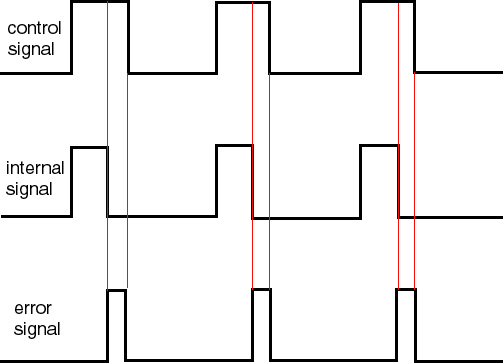
The motor is driven in whichever direction is required to reduce the error signal to 0, or very near 0. The width of the internally generated pulse is controlled by a feedback potentiometer attached to the output wheel at the end of the servo motor gear train. This is the pot that is removed or disconnected in the various servo-hack schemes when used for endless rotation to drive robot wheels.
The servo electronics compare the pulse width of the incoming control signal with the pulse width of the internally generated signal. If the incoming signal is larger it drives the servo motor in one direction, and if it is smaller it drives the motor in the opposite direction.
Normal R/C Servo Output Motor and Feedback element:
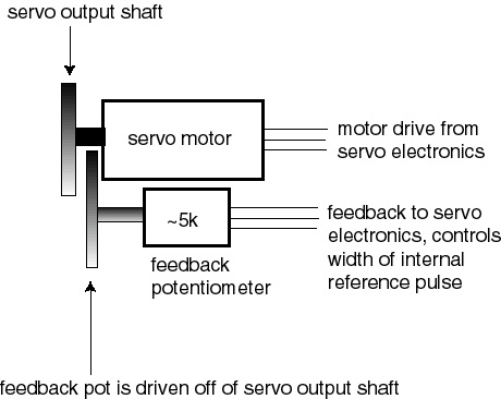
These pots are typically a 5k linear taper, or something similar. As the motor drives the output wheel, it turns the pot, which changes the width of the internally generated pulse, forcing it to match the width of the control pulse. When the two pulses are the same width, or very close to the same width, the motor is turned off.
This "very close to the same width" is the source of the servo dead zone. Most modern servos also vary the motor speed such that the motor runs more slowly when the two pulse widths are close to the same, to prevent "hunting" and servo chatter near the dead band, but still be able to drive at full speed when the pulses are very different. Some robot builders have been able to exploit this feature to provide some limited variable robot speeds from their hacked servos.
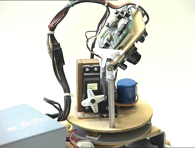
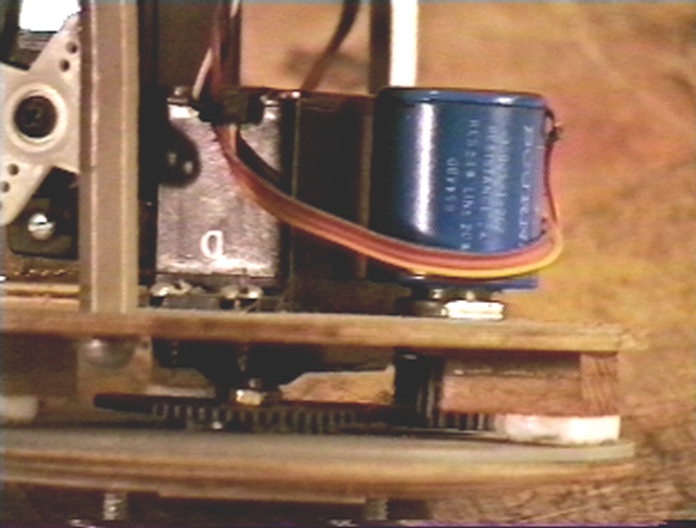
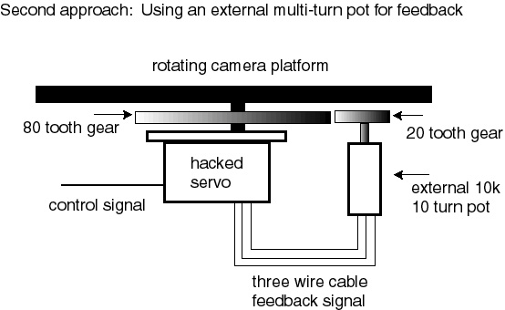
Our solution for increasing the positioning accuracy of the servo head was to drive the head directly from the servo output and use an external pot for the positioning feedback. Once the internal pot has been disconnected and removed, the servo output can rotate endlessly until the external pot is driven into range. The output and feedback pot can then be geared up or down to whatever positioning accuracy is required.
For our camera platform, we attached an 80 tooth gear ring to the outside of the platform base. We used a 20 tooth gear on a 10 turn pot, so one full revolution of the platform mapped to 4 complete turns of the pot, and 5 turns of the pot gave us the full range of the servo movement. This way we are not gearing up the servo position error x3 as before.
The construction sequence is:
1. Open servo and remove and/or disconnect the feedback servo from the output gear train.
2. Find where the three wires from the pot connect to the servo printed circuit board. Un-solder the three wires and solder in our own three wire flat cable.
3. Re-assemble the servo, enlarging the access hole for the control wires to allow the new three-wire flat cable to pass though.
4. Select an appropriate multi-turn pot for your application.
For the rotation we wanted, a 10 turn 10k pot worked out exactly. Solder the three-wire flat cable wires to the terminals on the external multi-turn pot. Be sure to keep power, signal, and ground in the right order.
5. Mechanically couple the multi-turn pot to your output device :)
To test the servo, power it up and give it a nominal (1.5 milsec)control pulse. The motor should start running, and the output shaft will rotate. You should be able to turn the external multi-turn pot with your fingers until the motor slows and finally stops. Continuing to turn the pot should start the output shaft rotating in the opposite direction, slowly at first, and then faster as you continue the rotation.
This is the setup we are currently using and it works just dandy. The robot head can rotate all the way around about 15 degrees past backwards, and still reposition itself accurately when the controls are centered.
Because the feedback device is directly connected to the final output platform, this corrects for slop and backlash in the driving mechanism that might cause overshoot or undershoot. The servo motor continues to drive until the final output stage is in the correct position, irrespective of slop in the gear train.
hope this is useful, happy roboting,
19 September 2000
Dallas, Texas
dpa