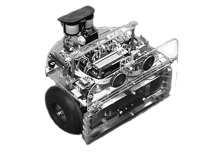
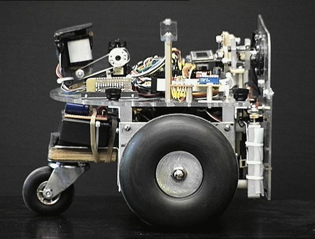
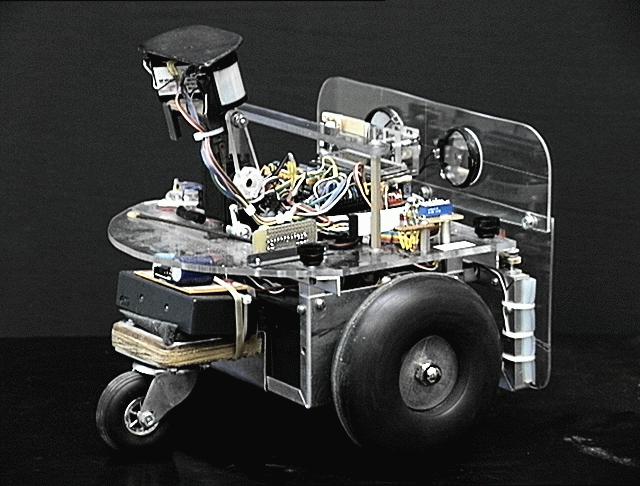
SR04 is a small mobile robot suitable for exploring human habitats unattended. It is controlled by a Motorola HC6811 microprocessor running in an M.I.T. 6.270 CPU card, similar to the commercially available "Handy Board." Two 12-volt DC gear-head motors maneuver the robot in a dual-differential drive configuration, balanced by a non-driven tail wheel caster and powered by a 12 volt 2.2 amp-hour sealed lead acid battery. Sensory input is provided by (in order of priority): front bumper switches, IR collision avoidance, stereo sonar ranging, photo detectors, passive IR motion detection, and shaft-encoder odometry.
This is my fourth robot project,
the prior three were constructed with Lego Techniques ® and variously
controlled by analog hardware, a New Micros HC6811 Forth CPU, and the "Rug
Warrior" CPU card sold in conjunction with Flynns excellent "Mobile Robots"
book. This design has evolved from those robots and from many long conversations
with friend and veteran robot builder Duane Gustavus.
© 1998 David P. Anderson,
Department of Geological Sciences,
Southern Methodist University
I. Design.
The SR04 was conceived around the following very loose design criteria:1. Survive in a wide range of (cluttered) human environments autonomously and continuously, without getting stuck.
2. Provide a robust and reliable platform for developing navigation and behavior software.
3. Be entertaining and aesthetic for the local human population.
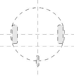
A. ChassisThe design which has emerged is a small dual-differential drive platform with the geometry of an 11" circle. The drive wheels and tail caster sit on the perimeter of this circle, and thus it can rotate in it's own space. This greatly simplifies software for maneuvering and collision avoidance.
B. CPUThe robot controller is a Motorola HC6811 microprocessor running in an M.I.T. 6.270 board. This card was developed for the introductory robotics course taught at M.I.T. It provides the HC6811 processor with 32k of battery-backed RAM, 32 eight-bit A/D channels, hardware 40khz IR , 6 one-amp H-Bridge (L293) motor driver channels, an LCD readout, and some digital I/O ports for timer and output compare functions useful to robot builder-types.
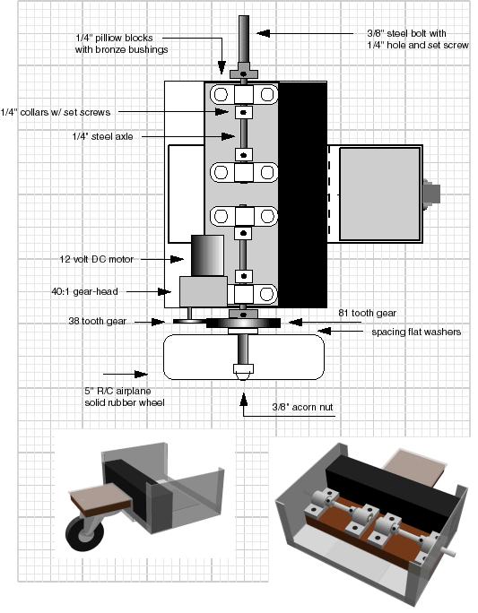
The SR04 chassis is constructed from the bottom half of a 3"x5"x7" aluminum "bud" box. A folded aluminum bracket bolted to the bottom of the box mounts the 2" tail wheel caster. The main drive wheels are 5" solid rubber model airplane wheels mounted on ¼" steel shafts that are supported by pillow blocks with ¼" bronze bushings. The pillow blocks are bolted to a 1" wooden spacer that lowers the center of gravity slightly and also pins the lead-acid battery in place.
C. Development EnvironmentThe software environment for the board is an interactive p-code interpreter called "ic" which compiles not quite ANSI standard C source. It comes with a multi-tasking kernel and an extensive library of subroutines for things like pulse-width modulation, shaft-encoder routines, and IR detection.
The software for the robot was all developed and tested in the ic p-code environment, but I have recently ported the whole thing to ImageCraft's "icc11." The new compiled code runs about 10 times faster than the interpreted p-code, and allows me to manipulate the memory map in a more complex fashion. (I got back 10k of memory space!)
D. SoftwareThe SR04 software exists as a collection of sensor routines and associated behaviors that are run concurrently by a round robin, non-preemptive multi-tasking scheduler. The structure is loosely based on Rodney Brooks' subsumption architecture as describe in Flynn's "Mobile Robots" book and more extensively on Brooks' home page (and elsewhere, run a web search on "subsumption").
Each sensor routine runs in turn in a 20 Hz sensor loop, and each sets a flag and some variables based on it's own particular sensor input and state. An arbitration routine then picks the flag with the highest priority and passes it's variables along to the motor control sub-system. In this manner, sensors with higher priorities "subsume" the behaviors of lower priority sensors.
The priority scheme is based on the distance of the detecting event. Closer events have higher priority; more distant events have lower. The exact sequence is:
0 User
1 Bumpers
2 Rotation and Scanning
3 IR Collision Avoidance
4 Sonar Ranging
5 Photo Approach/Avoid
6 Motion Detector
7 Dead-reckoning
Thus the Sonar ranging layer can subsume the Photo, Motion, and Dead-reckoning layers when it detects an obstacle or clear pathway. It is in turn subsumed by the IR collision avoidance, and the Rotation and Scanning behavior subsume both. The Bumper layer holds the ultimate control. All other tasks save the User (thats me) must give way if the robot has actually run into something, until the bumper behavior declares the robot to be free from obstructions. This formalization is an extremely useful way to organize multiple and potentially competing sensor inputs.
III. Subsystems.
A. PID controller.A Proportional Integral Derivative (PID) algorithm is used to control the main drive motors and maneuver the robot. This useful and subtle control method consists of three subsystems:
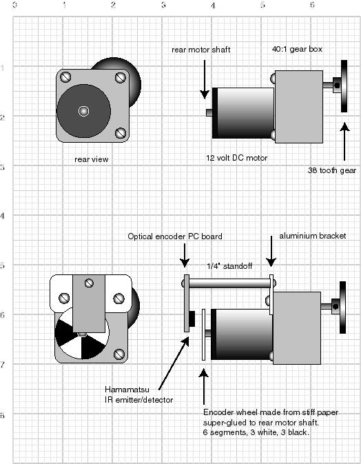
1. Shaft encoders.Optical encoders attached directly to the motor shafts are used to accurately measure the speed of the motors (and by inference, the position of the robot).
2. Pulse Width Modulation
Hardware timer interrupt generators in the HC6811 chip are used to generate two PWM sign
als that control the two L293 H-Bridges, which drive the main motors.3. PID
The PID algorithm itself runs in the 20 Hz sensor loop. It samples the shaft encoder variables to determine the current motor speeds, compares these to the requested motor speeds, and adjusts the PWM values up or down to get sampled and requested values to match.
This method of closed loop control has a number of advantages. The velocity of the robot becomes independent of battery voltage, as the PID controller will increase the pulse width to make up for the sagging supply. It is also independent of load, so the robot can move very slowly and still climb over objects and maintain constant speed on an incline. The ability to control the wheels smoothly over a wide speed range translates into the ability to precisely maneuver the robot. The PID controller also provides stability for dead-reckoning algorithms.
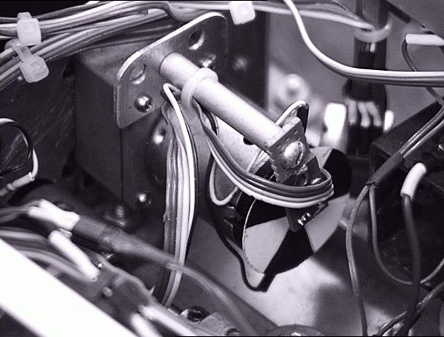
B. OdometryThe encoder counts returned from the optical shaft encoders mounted on the drive motors are also used to track the position of the robot relative to it's position when last reset. These are maintained as a set of global variables that are updated at the 20 Hz sensor loop rate. X_position and Y_position are the Cartesian co-ordinates in inches, and Theta is the rotation of the 'bot around it's center in degrees. These data provide the "sensor input" for the dead-reckoning behaviors.
C. Telemetry
A pair of "Lynx" radio tx/rcv modules is used to implement a telemetry back channel. The robot transmits a continuous stream of 80 character ASCII packets at 2400 baud. These consist of odometer and sensor data, battery voltage, state flags, and so forth. These are received and piped directly to the computer screen, or tee'd off to a file for later perusal. The transmitter on the robot draws only about 10 ma and is useful out to around 50 feet, depending on the space.
IV. Sensors and Behaviors
A. ProwlThe lowest priority behavior is to "prowl." This behavior takes one of two states:
1. Target = 0;No dead-reckoning target. Default behavior is to move forward and attempt to slew motor speed to the top speed set by the user.
2. Target != 0;
We have a dead-reckoning target. Using the odometry variables as sensor inputs:
a. Determine distance and heading to target.
b. Generate a turn_left/turn_right command based on difference between current heading and target.
c. Generate a motor speed based on distance to target, i.e., slow down as we approach.
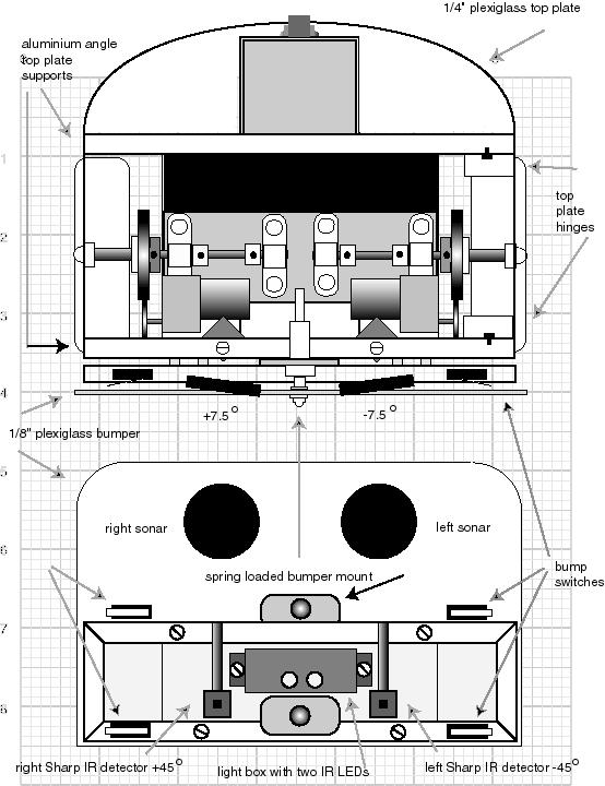
B. BumperThe bump sensors drive the highest priority behavior. This is also by far the most complex of the behaviors, with the largest number of possible sensor states. The Plexiglas front bumper has 6 switches arranged as 3 pairs in series to transduce bumper presses on the left, right, and center. The CPU reads these directly as 3 digital I/O switch closings.
The default behavior is simple: on receiving a bumper press, back up and rotate away from the bump. Thus a right bump turns the bot to the left and a left bump turns it to the right. A center bump calls a random number generator to determine the appropriate direction. This algorithm works about 95% of the time, but it can get caught in corners, inside acute angles, and especially by the Evil 5-Legged Black Office Chair (I have several).
SR04 has two escape mechanisms, one which looks for the right-left-right-left pattern of an inside corner, and one which looks for too many bumps happening in a short period of time, with no forward progress. In both cases, the bot just spins 180 degrees and tries again. This usually works, though not always the first time.
A second set of bumper behaviors has to do with working free from a jammed bumper condition. This can happen if the robot drives over something and hangs its bumper, or gets something caught on the backside of the bumper. The condition that is noted is that the bumper press has been continuous for a certain period of time. In this case the bumper behavior enters a sequence where it twists left and right and drives forward and backward at various speeds while ignoring the bumper press, waiting for it to release.
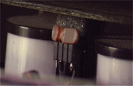
C. Photo CellsA pair of cadmium-sulfide photocells are used to read the ambient room lighting. These are connected directly to two of the 6.270 A/D channels, where they act as variable voltage dividers in series with the pull-up resistors. These return values between 0 (very bright) and 255 (quite dark) for each channel.
There are two photo behaviors determined by the photo avoid flag:
1. Avoid = 0This simple navigation algorithm can produce some really sophisticated results. In the simplest case, the robot will swim toward a bright light source and circle it like a moth, in photo attract mode. In more subtle ways, it will navigate a room, avoiding shadows and seeking out open pathways around objects. This mode requires the bumper behavior running to provide collision protection.Difference the left-looking and right-looking photo cell values and generate a turn left/turn right command towards the brighter side, if the difference is larger than some arbitrary "deadzone" (i.e., don't hunt around zero).
2. Avoid = 1
This is the same as above, but turn AWAY from the brighter side rather than towards it.
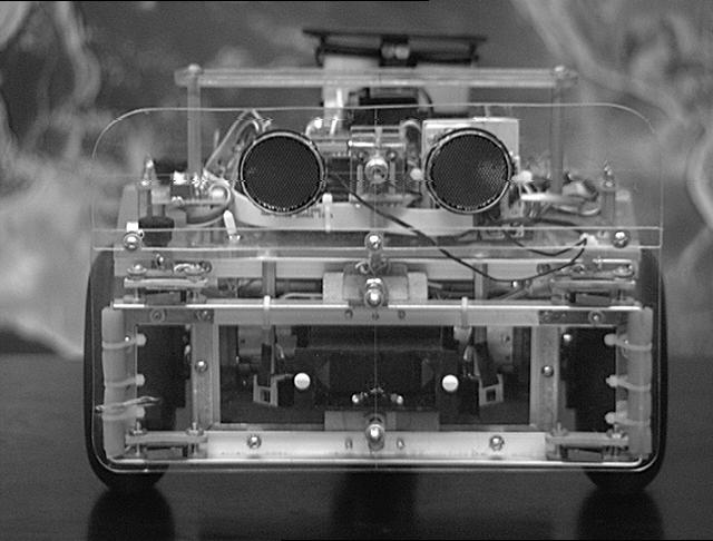
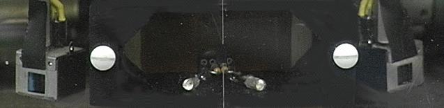
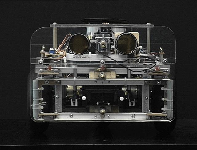
D. IR detectors. 1. PhysicalInfrared collision avoidance is provided by two infrared LEDS mounted in a shadow box in the front bumper, and two Sharp IR detectors mounted on either side, pointing off at 45 degrees from the centerline. These can detect reflected IR energy out to about 30 inches, and are arranged so that they share a slightly overlapping area in the center.
2. IR Modulation
The 6.270 board hardware provides a 40khz signal to drive the IR leds as required by the Sharp IR detectors. This signal can be switched on and off in software. This is used to help eliminate false detections from ambient IR. The detector code now running in the bot further modulates the IR leds at 125 Hz in software. The code runs once each half cycle (250 Hz), and signals IR detection if it reads a detect when the IR leds are on, and no detect when the IR leds are off.
3. IR Detection
IR detection requires a certain number of continuous detects before signaling a collision avoidance behavior. This number is kept in a variable, max_count. Low max_count values cause the robot to respond more sensitively to fewer detects, to the point of quivering in the center of the room. Larger max_count values cause the bot to respond more slowly but more positively to IR detections, to the point of not "avoiding" the impending collision at all.
The SR04 IR behaviors now running use an adaptive mechanism that sets max_count based on the number of detections. Few detections lower max_count and increase the "sensitivity" of the system, while more detections raise max_count and reduce the sensitivity. This allows the robot to explore an area and maintain it's distance to walls and objects, yet still be able to penetrate a confined space by automatically increasing max_count and lowering its sensitivity to IR detections.
4. IR Behaviors
There is one escape state, for
the IR jammed condition, signaled when one or both IR detectors have been
on continuously for a long time (30 seconds). The response is to turn the
IR off for a fixed period (30 seconds).
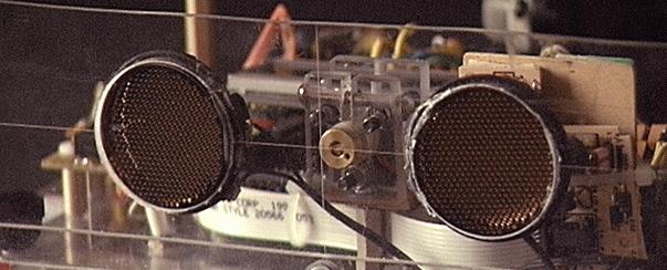
A pair of Polaroid 6500 Ultrasonic
rangers is mounted in the front bumper, each offset 7.5 degrees away from
the centerline of the robot. These units send out an ultra-sonic "ping"
and time the arrival of the first echo to determine distance. The beam
width is quite narrow, about 15 degrees, so mounting them offset by 7.5
degrees provides a left and right view without a blind zone in the center.
The two sonar modules are driven from the L293 H-Bridge socket on the 6.270 expansion board, with the L293 removed. This provides 6 I/O lines for controlling the two modules. The output lines (ECHO) of the two boards are tied to two digital I/O ports on the main board.
3. Behavior
The sonar driver code returns distances from 3 inches to 35 feet in one-inch increments. The default behavior is to generate a turn_left/turn_right command toward whichever side is longer, as long as the difference between them is larger than some deadzone. The deadzone is calculated as a percentage of the total distance. The distance determines the amount of turn, with sharper turns for closer objects.
If both sonars return distance
of less then some arbitrary value CLOSE (30 inches) then velocity is set
to zero, and the robot can rotate but not move forward, as with the IR
dual detection behavior.
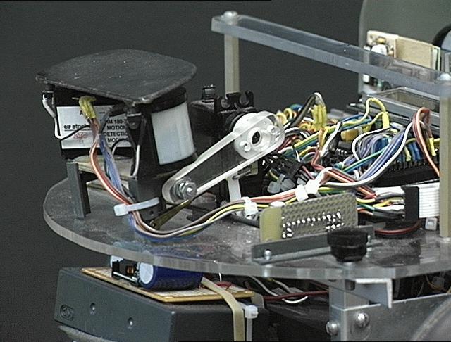
Two passive infrared motion detectors are mounted on a servo arm at the rear of the robot. These generate a signal when a suitably warm-blooded mammal passes through the field of view. The sensors cannot see through the Plexiglas front bumper that protects the robot while it is in motion, so they are raised above the bumper on the servo arm when the robot is at rest. A switch mounted "top-hat" serves to detect if they are being raised up into anything.
2. Electrical
The motion detectors generate a 0-5 volt logic signal suitable for direct connection to a digital I/O port. Piece of cake.
3. Behaviors
The motion detector code monitors
the motor speeds looking for an average left and right speed of 0. When
detected, the following sequence of states is executed:
When a motion detect occurs, the robot retracts the servo and charges at full speed briefly in the direction of the detect, left,right or forward. This can get quite a rise out of the cat.
G. Dead ReckoningThis routine runs as part of the "prowl" behavior. It takes a list of X,Y coordinates specified in inches, sets the X_target and Y_target values used by "prowl," and sets TARGET = true. It then waits for prowl to reset TARGET back to 0, indicating the target has been reached, and gets another X,Y point from the list. When the end of the list is reached, it shuts down the robot and sings the "I'm Finished With The Co-ordinate List" song.
I originally developed this mode to compete in the DPRG (Dallas Personal Robotics Group) contests, but I have now found a whole new set of nifty behaviors that spring from the same basic code. Lately I have added a mode that allows the bot to wander freely about a space for three minutes, and then sound an alarm and try to dead-reckon back to the origin. This becomes very interesting if the path back to the origin has been blocked. I have seen the robot actually leave the room, go around the house, re-enter through a different doorway and finally back to the origin.
H. Passive BehaviorThis detector triggers based on certain sequences of bumper events, which are variable. When it fires, it executes the following sequence of states:
1. Spin robot through 360-degree scan, measuring sonar, IR, and photo every few degrees.This is a pretty fun behavior. Ill be sitting at my desk working while the robot wanders the house and Ill realize that I dont hear it anymore. So I get up and go look for it and it is invariably hiding behind a door or a couch and leaps out and startles me as I walk by. My wife is not fond of this particular mode.
2. Rotate toward direction where humans might be, based on the longest sonar, brightest light, and largest IR null.
3. Set robot speed to zero, thus implicitly enabling the motion detectors.
4. Sing a nice song, and wait for motion detectors to fire.
5. ExitI. Reactive Behavior
What I term reactive behavior is a mode in which all of the sensor layers are active except the "prowl" layer. In this case the default behavior is to sit still unless there is some sensor input. Sonar, IR, bumper, and photo inputs cause the robot to "react" and try to move to an area where there are no detects. The end result is that it will wander around the room being pulled different directions by different sensors until it finds a spot where all sensors are null, and then it stops. Turning on a light or moving around the room and thus changing the ambient lighting or the sonar reflections will cause the bot to fire back up and try to find a new spot.
J. Combinations
These behaviors in different combinations produce very different results. For example, the sonar range finders tend to get lots of false readings from reflections when the robot is very close to a wall or other bright reflecting source. This generally causes it to turn toward an object rather than away when the beam is at a certain very critical angle. When the IR is running also, it will subsume the sonar behavior for close obstacles, and thereby prevent these false readings from controlling the path of the robot. The sensors are switched on and off by a "Behavior" layer, based on sensor inputs and sensor detection history.
V. Future Enhancements
A. Avoiding StepsAn autonomous robot turned loose in a normal human environment must deal with the problem of steps. Most specifically, even if the robot cannot climb up stairs, it must be able to avoid falling down them. This requires some method of sensing an edge or drop off.
B. Foraging for power
The ability to charge its own battery would give the robot a huge leap toward total autonomy. Some sort of charging station, or perhaps an array of solar cells. Currently the robot does the same thing as my boys when low on power: it calls me.
C. Two-way Radio Link
The telemetry link that is implemented is a one way communication; the robot can talk to the computer but not the other way round. It seems like the potential intelligence of the behaviors would go up if a two-way link could allow the host computer to analyze the telemetry data in a more intensive manner than is possible with an embedded controller, and send commands, or at least suggestions, back to the robot.