
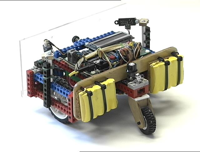
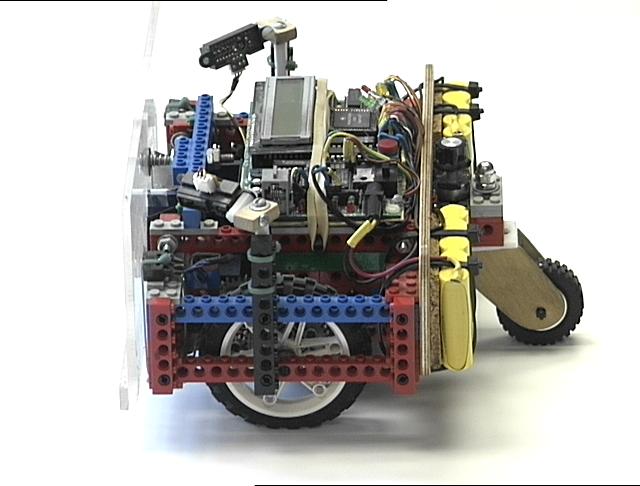
Power for the motors and microcontroller is provided by ten 1600 mAh NiMH cells split into two
five-cell packs. The packs are mounted on the plywood spine on either side of the
tail wheel. This mounting arrangement serves to locate the robot's center of gravity
about one inch behind the main drive wheels and so prevents the robot from tipping forward
on it's nose during rapid maneuvers, while still providing enough weight on the main
wheels to insure good traction.
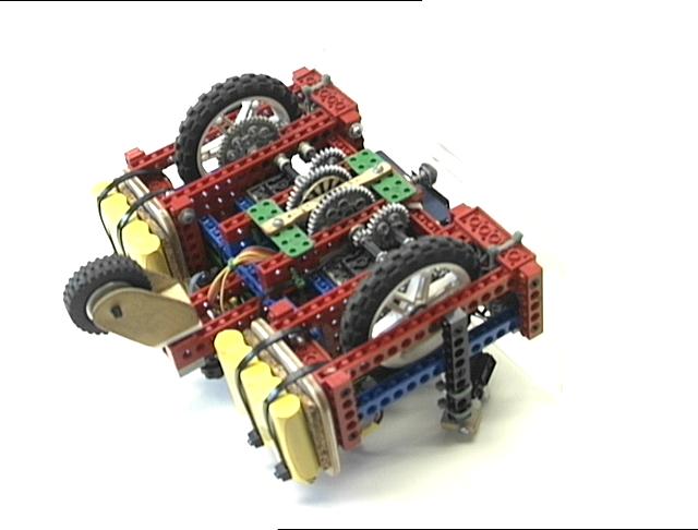
The robot uses a dual differential drive mechanism for propulsion and steering. A pair of
Lego motors and three sets of 40:8 gears provides a 125:1 gear reduction. The spur gears that
are driven directly by the motors have 32 segment black-and-white encoder patterns glued to
the gears. These are read optically, similar to the
home brew shaft encoders, to provide motor feedback for velocity control
and position calculations, commonly referred to as
"odometry."
The Hamamatsu photo reflector
optical elements are
attached to the plywood strut connecting the two green Lego blocks, which can been seen in
the above image situated just between the two output shafts.
The drive wheels are balanced by a non-driven castering tail wheel. It is constructed from
a small Lego wheel and two plywood side panels. A Teflon bearing surface on the top is
held in contact with the Lego tail struts using a steel bolt and a chrome acorn nut. A knob
used for inputting software parameters can be seen just in front of the tail wheel assembly,
mounted behind the plywood spine.
The LegoBot has four sets of sensors which it uses for autonomous navigation. The optical
shaft encoders described above provide the raw data for location (X,Y) and rotations (Theta)
in inches and degrees, respectively. Using these the robot can keep
track of its position
and navigate toward a target, or a list of targets. Most of the contest behaviors which the
robot can do utilize this navigation ability in one way or another.
Here is an mpeg movie of a simple navigation exercise. The robot
has a single target, 8 feet directly ahead. When it arrives at the target it slows down and
comes to a halt, pivots 180 degrees to face the starting point, and then returns to the
starting point, and rotates back to its original heading. This exercise could also be
accomplished with more traditional robot dead reckoning, or even more simply by a timing pattern.
However the robot is tracking its location 20 times per second and re-calculating the shortest path
to the target each time. This is more apparent when the other sensors become active.
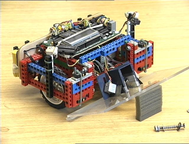
A second set of sensors consists of four microswitches mounted on the front of the chassis
that are activated by the clear plastic Lexan front bumper. The bumper is mounted in the
center on a pair of spring-loaded bolts. In this way the robot can detect bumper presses
on the left, the right, and in the center. In the image above the front bumper has been removed
from it's mounting bolts to reveal the location of the microswitches, which are bound in place
with green cable ties.
The platform's reaction depends on the location
of the bumper event. Detections on the right cause the platform to back up slightly and
pivot to the left, while detections on the left cause it to back up slightly and pivot to
the right. Center detections cause the robot to back away and rotate 90 degrees, left
or right as determined by the bumper detection history. The microcontroller keeps a history
of the timing and location of the 12 most recent detections, and the robot uses
this information to work it's way free from entanglements and complex environmental geometries
like chair legs and power cords.
Here is another mpeg movie of a slightly more complex navigation
exercise. Again the robot has a single target 8 feet directly ahead, but in this case there
is an obstacle, the ubiquitous 5-legged office chair. This autonomous navigation problem
combines the target acquisition behavior of the odometry with the obstacle avoidance behavior
of the bump sensors. The straight line calculations of the first exercise are interrupted
by collisions with the chair legs, and the robot's continuous re-calculation of its
location and the shortest distance to the target are apparent. The ultimate path the
robot travels is considerably longer than 8 feet, and in this case dead-reckoning
or timing patterns cannot accomplish the same behavior.
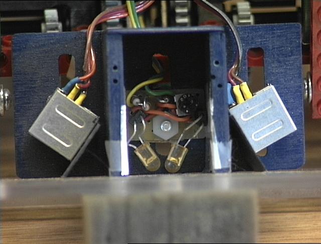
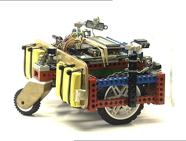
The third set of sensors consist of Infrared (IR) emitter and detector pairs mounted in a
shadow box behind the front bumper. They are arranged such that they illuminate and detect
objects in two overlapping lobes in front of the robot, out to a distance of about 15 inches.
In the image above the two IR LEDs are the yellowish objects angled toward each other in the
center of the shadow box. The IR detectors are the two silver boxes angled away from center
on either side. The elements are mounted and shielded in such a way as to provide two
separate fields of view of equal detection strength, with a slight overlap in the center.
Visible light indicator leds, green for left and red for right, are mounted on the CPU and
are lit when a detection occurs in either or both zones.
The reaction of the robot to IR detections is something like that for bumper detections. For a
detection on the right the robot steers to its left, and for a detection on the left it
steers to its right. When there is an IR detection in the center, the robot slows its
forward speed, which then takes some time to build back up. This has the effect of slowing
the robot down more and more until it comes to a stop, unable to proceed forward but still
able to pivot left or right. This behavior is very effective in avoiding
obstacles and maneuvering in a tight space.
Here is a third mpeg movie of the robot going forward 8 feet
and back while using its IR sensors to avoid a cardboard box. The initial detection of
the box pivots the robot around to the right too far to clear the obstacle, and it continues
turning right until it no longer detects the desk legs or the wall. At that point it
is able to find the shortest distance to the target and navigate between the box and table
legs to its goal. A white paper napkin has been placed on the floor to use as a guide for
judging the accuracy of the robot's return to the point of origin. Looks like it missed
by an inch or two.
These three sets of sensors together can allow the robot to operate robustly in a cluttered
human environment (which mine always is.) The bumper behavior, as the "sensor of last
resort" runs only rarely, but it is necessary to protect the robot from damage and from getting
stuck when the other sensors fail. It is exactly the same height and depth as the tallest
and lowest components of the robot, so if the bumper clears an obstruction the rest of the
robot will also.
Here is a somewhat longer mpeg movie of the robot navigating around
the same room and avoiding obstacles and entanglements. In this case it is not navigating
to a particular target but rather seeking to explore the entire extent of this "unknown"
environment. Notice the IR detectors seem to effectively avoid the gray 5-legged office
chair but have a hard time with the silver one, calling on the bumper behaviors at least
once to get past the "invisible" legs.
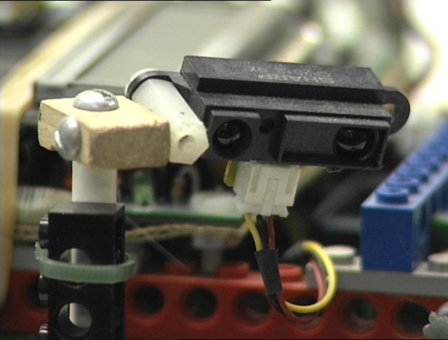
The final set of sensors on the LegoBot are a pair of
Sharp GP2D12
IR proximity detectors.
These are mounted on uprights with 3-axis pivots directly behind the front bumper
on either side. They are angled to point slightly forward, out left and right from center,
and down toward the floor. These sensors return an analog voltage proportional to the
distance of a small focused spot of IR light projected by the sensor, and are accurate
from about 3 inches to around 30 inches. The Legobot uses these sensors to measure
the distance to the nearest wall or other objects in order to perform a wall following,
or perimeter following, navigation mode.
In this wall-following mode the robot's path is directed by a combination of the normal
IR detectors and the Sharp proximity detectors. When the distance to the wall becomes
too great as measured by the proximity detectors the robot turns toward the wall. This
is signaled visually with a blue indicator LED (had to find a use for one of those cool
BLUE LEDS!) When the robot approaches too close to the wall the normal IR collision
avoidance sensors steer it away. So between the two sets of sensors, the robot can
find a path parallel to a wall and follow it around the room, or around the building.
Here is a wall-following mpeg movie of the robot navigating
down a long hallway in the Heroy Science Building at SMU. The robot begins facing the
wall and rotates to acquire a right-following mode. In this mode the left-facing Sharp
detector is inactive. The robot attempts to maintain a constant distance from the
wall, about 12 inches. The curvature of the turn is controlled by the distance to
the wall, so that the robot makes mild corrections while following the wall and is
still able to turn sharply around corners and posts and other obstacles along the path.
This navigation technique is not limited to hallways with nice even boundaries. The
robot can also track along the perimeter of almost any object (like for example it can
circle me when I'm sitting on the floor) or even an irregular set of objects.
Here is a perimeter-following mpeg movie of the robot navigating
the outline of the clutter in my office. In this case the distance to the wall is automatically
increased to account for the large number of IR collision detections that the robot
is reading. Even without the advantage of nice flat walls for IR detection the robot is
able to following the outline of the room and avoid collisions and obstructions.
Most of the robot competitions that LegoBot has entered have very simple geometries and
reflecting surfaces by comparison, and so its performance has been generally applauded. But
it is in a cluttered, disorganized, and ultimately human environment that robots must
eventually operate, and that which LegoBot attempts to pursue.
Happy Roboting.
02 August 2002
Dallas, Texas
dpa
Back to my Robots homepage.