Calibration for the
RCAT robot
16 October 2018
dpa
This page grew out of a post for the Dallas Personal Robotics Group mailing list. It was inspired by some experiments we ran with my RCAT robot last Saturday at the Microsoft headquarters in Dallas (Irving?) and some ensuing questions about the robot's calibration.
---------------------------------------------
Howdy DPRG,
After spending some time free-roaming the kitchen and finding it's way home at the gathering on Saturday, we had the rcat robot run a 15 foot UMBMark calibration square demo, and I was asked some questions about the robot's odometery and calibration. I thought it might be useful to see the actual numbers rcat is using and describe the way they were derived, by way of an example for others working on similar problems. Plus I have these data and colorful graphs.
The Function
For context, the rcat robot samples its motor encoders and runs odometery calculations 25 times per second. The number of encoder counts for each wheel since the last sample are returned in the integer variables "left_velocity" and "right_velocity." The function which calculates the robot's position, X_pos and Y_pos, and its orientation, theta, in floats, looks like this:
{
/* sample both motor encoders as close together as possible */
left_velocity = read_left_encoder();
right_velocity = read_right_encoder();
/* calculate wheel travel in inches */
left_inches = (float)left_velocity / LEFT_CLICKS_PER_INCH;
right_inches = (float)right_velocity / RIGHT_CLICKS_PER_INCH;
inches = (left_inches + right_inches) / 2.0;
/* calculate and accumulate orientation from wheel difference */
theta += (left_inches - right_inches) / WHEEL_BASE;
/* clip at +-360 degrees */
theta -= (float)((int)(theta/TWOPI))*TWOPI;
/* calculate and accumulate global position in inches in X and Y */
X_pos += inches * sin(theta);
Y_pos += inches * cos(theta);
}
The Constants
The constants that need to be derived from the robot's geometry for this function to be calibrated are WHEEL_BASE, LEFT_CLICKS_PER_INCH, and RIGHT_CLICKS_PER_INCH.
It turns out to be easier to tweak the calibration if the left and right clicks are defined as a single CLICKS_PER_INCH and a WHEEL_SIZE_ERROR that is added to one wheel and subtracted from the other. This is required because no two wheels are actually ever the same size. This shows up as asymmetries in the robot's behavior. It causes the robot to arc ever so slightly in one direction when it thinks it is traveling a straight line. The effect can be subtle, but measurable.
#define LEFT_CLICKS_PER_INCH (CLICKS_PER_INCH + WHEEL_SIZE_ERROR)
#define RIGHT_CLICKS_PER_INCH (CLICKS_PER_INCH - WHEEL_SIZE_ERROR)
1. Clicks Per Inch
The robot was manually driven in a straight line for 50 feet (down the hallway outside my office), and stopped when it reached a previously measured 50 foot mark, and the total left and right encoder counts recorded. I did this 3 times and averaged the results:
50 feet Average Left encoder counts = 2301622
50 feet Average Right encoder counts = 2309276
and then averaged the two and divided by inches to get clicks per inch:
(2301622+2309276)/2 = 2305449.00 / (50*12) = 3842.415 clicks per inch
#define CLICKS_PER_INCH 3842.415
This number is way more accurate than will ever be needed and does not generally have to be further tweaked as the robot is calibrated.
2. Wheel size error
The starting value for WHEEL_SIZE_ERROR, the difference in size between the wheels which does need to be calibrated, was calculated as:
((left_encoder-right_encoder)/inches)/2 = ((2301622-2309276)/(50*12))/2 = -6.3783
#define WHEEL_SIZE_ERROR -6.38
For calibration, making WHEEL_SIZE_ERROR more negative makes the robot turn more left, and more positive turns more right.
3. Wheel base
Finally the robot's initial WHEEL_BASE, the center to center distance between the wheels which also must be calibrated, was measured in inches with a steel rule:
#define WHEEL_BASE 11.50
As seen in the function above, the wheel base forms one side of a right triangle, with the robot traveling along the hypotenuse, every 25th of a second. For calibration, making the WHEEL_BASE larger will make the turns tighter. Making the WHEEL_BASE smaller will make the turns looser.
Calibrating with The UMBMark
The strategy of the UMBMark is a calibration test that can be used to separate out the errors caused by inaccurate WHEEL_BASE from the errors caused by inaccurate WHEEL_SIZE_ERROR. This is done by running a series of patterns around a square, both clockwise and counter-clockwise, and recording the error in the position when the robot returns to the origin. The square can be any size, the larger the better for seeing the errors. Here's a link to the original paper:
UMBMark.pdf
If the WHEEL_BASE value is too small, all angles will be too small, and the robot will return south of, and short of, the goal. If it is too large, all angles will be too large and the robot will end up overshooting, and north of, the goal. Wheel base errors are symmetrical, clockwise and counter-clockwise. Conversely, wheel size errors are asymetrical, as the robot is turning too tight in one direction and too loose in the other.
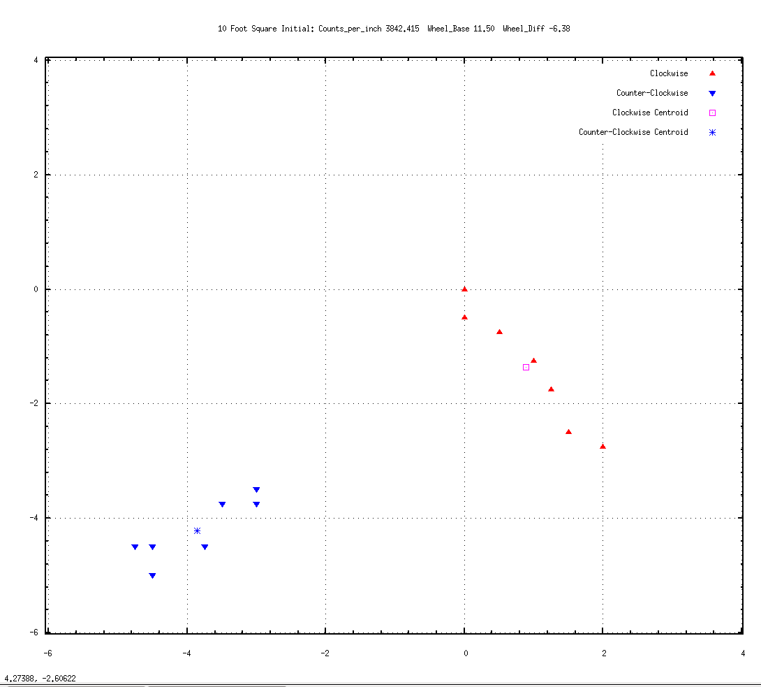
Here are seven runs around a 10 foot square clockwise (red) and counter-clockwise (blue) using those initial values.
The triangles mark the stopping point for each run, when the robot believes it has arrived back at 0,0, the origin, after it's 40 foot journey. Divisions are in inches:
Wheel_BASE = 11.50, WHEEL_SIZE_ERROR = -6.38
Initial Calibration 01.png
The red triangles are for clockwise runs and so imagine the robot arriving from the right side of the graph and stopping centered on a triangle. Similarly, the blue triangles are counter-clockwise runs so picture the robot arriving from the left side of the graph. The average or "centroid" of the arrival positions is calculated and displayed as a pink square (clockwise) and blue asterisk (counter-clockwise).
As an aside, one of the clockwise runs landed back exactly at 0,0. If that had been the only test run, one might believe that the robot was indeed calibrated. The UMBmark suggests 5 runs each direction as the minimum needed to get a good average location.
Now at this point the UMBMark has some fairly complex math which can determine the correction iteratively and which I have never really mastered. Paul Boucher took a stab at it a few years ago but I'm not sure his solution works in all cases.
However, it turns out that one can use the UMBMark test results to "cut-and-try" empirically, and the solution converges pretty quickly.
It's sort of like sighting in a rifle scope: shoot a pattern, take the center, make adjustments, repeat.
Looking at the above graph, two things are apparent. 1) the counter-clockwise blue paths are not turning as tightly left as the clockwise red paths are turning right, and 2) both clockwise and counter-clockwise are not turning far enough. Both are landing short of, and south of, the goal.
This suggests that the WHEEL_SIZE_ERROR needs to be more negative (turn more left than right), and the WHEEL_BASE needs to be larger (all turns tighter). Here's a graph of 9 runs each way with those adjustments.
Wheel_Base = 11.60, Wheel_Size_Error = -7.333.
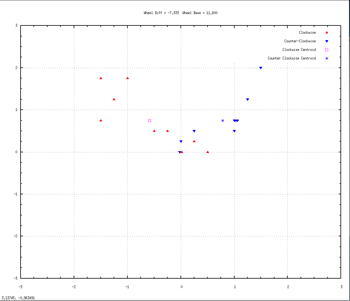
Calibration 02.png
The left and right centroids are now more symmetrical, suggesting that the wheel size errors are indeed canceling out. However, both clockwise and counter-clockwise runs are now turning a little too far, overshooting and landing north of the goal. So the wheel base is now a bit too large. Here's a graph of 7 runs with a slightly reduced wheel base:
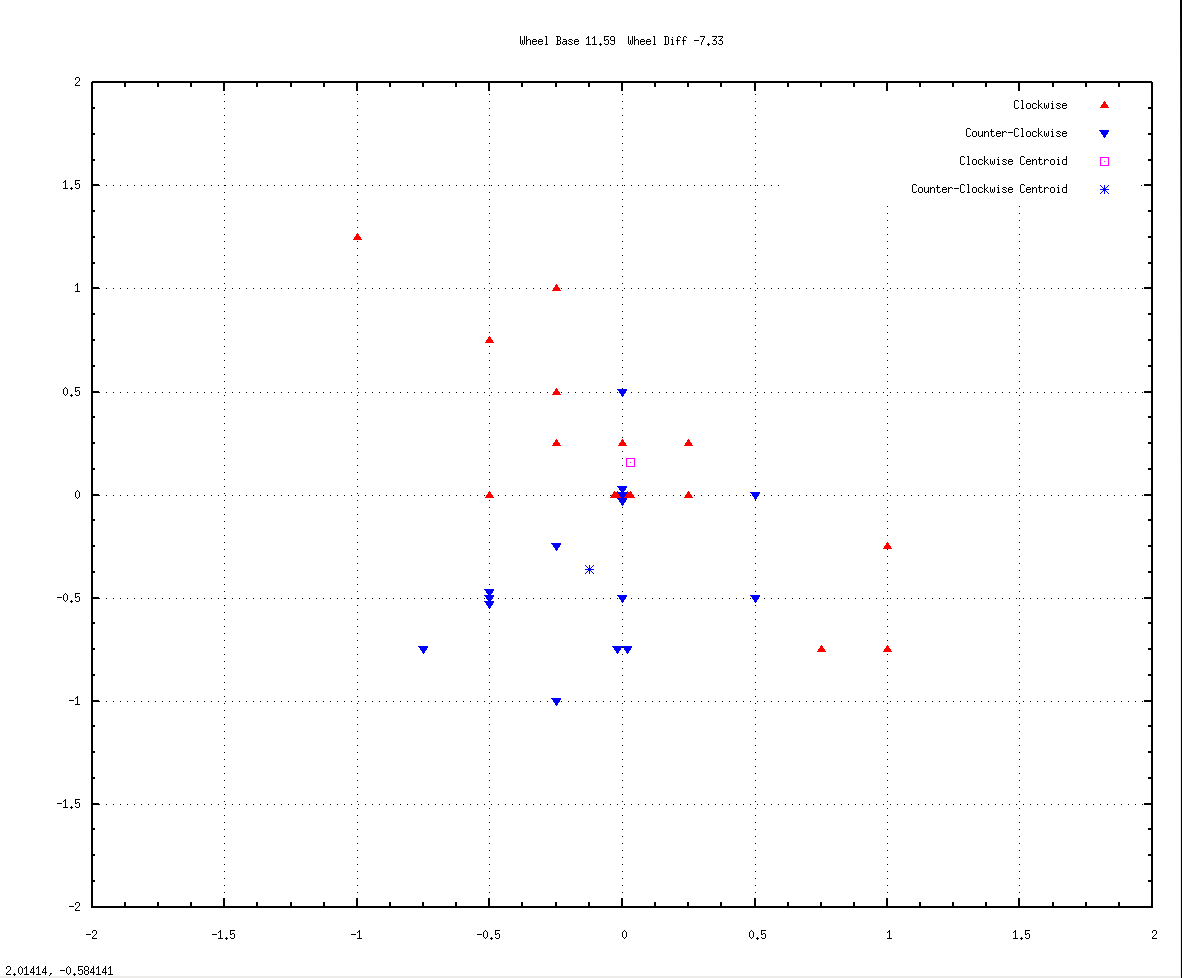
WHEEL_BASE = 11.59 and WHEEL_SIZE_ERROR = -7.33
Calibration 03.png
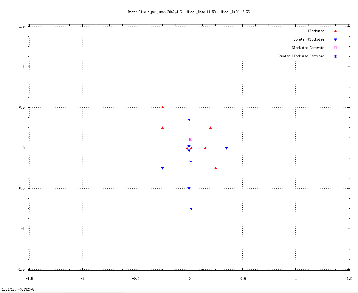
Not bad. The centroids are more or less symmetrical and both less than 1/4 inch from the goal. All but one or two of the arrivals are within 1/2 inch of the goal. And four of the runs hit 0,0 exactly --- two clockwise and two counter-clockwise, or about a quarter of the runs. The blue runs are still on average slightly undershooting, and the red are slightly overshooting, though that could be within the noise of my test&measurement. At any rate, I'm not sure I can do better than this. Here's a graph of 16 runs left and right with those same settings:
Wheel_Base = 11.59, Wheel_Size_Error = -7.33
Calibration 04.png
The blue centroid has moved some from the previous location, though still less than 1/2 inch from the origin. But the pink one is about in the same spot. And seven of the runs hit 0,0, four clockwise and 3 counter-clockwise, again about a quarter of the runs. About 60% of the arrivals are within half inch of the goal. The rest of the arrivals look scattered around 0,0 which is probably the best that can be done, short of becoming a better marksman (i.e., robot builder). This is the present calibration of the robot.
Hope this is useful.
cheers!
dpa
Last Update: 17 November 2018 dpa
