The Journey Robot
by
David P. Anderson and
Mike Hamilton
An Autonomous Six Wheel Off-Road Robot with Differential
All-Wheel Drive, All-Wheel Independent Suspension and Static/Dynamic Stability.
Click here for jBot's homepage, including videos of jBot in action.
Build Log for the Journey Robot.
Last update: 12 August 2005
I. Chassis
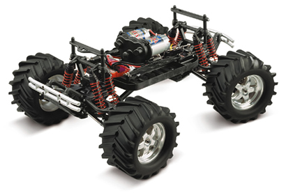 We began with suspension parts from a
Traxxas E-MAXX 4-wheel-drive 1/10 scale R/C
monster truck, which we bought used from a local hobby shop.
We began with suspension parts from a
Traxxas E-MAXX 4-wheel-drive 1/10 scale R/C
monster truck, which we bought used from a local hobby shop.
The E-MAXX is the electric version of the Traxxas T-MAXX. The suspension
parts for both models are the same, so either will serve for our purposes. These are very
nicely engineered suspension and drive parts, with a
full set of factory parts available, as well as lots of after-market components from various
manufacturers.
Traxxas' introduced the new-and-improved
REVO with it's nifty horizontal suspension, and so
a lot of used E-MAXX and T-MAXX have showed up on eBay and elsewhere, which provides a nice source of parts for
experimental robot builders.
 The suspension and drive for the front and rear wheels are identical on the E-MAXX, and both front and rear
can (potentially) be steerable, although that is not being used on jBot. The front and rear steering rods
are just bolted to the bulkheads.
The suspension and drive for the front and rear wheels are identical on the E-MAXX, and both front and rear
can (potentially) be steerable, although that is not being used on jBot. The front and rear steering rods
are just bolted to the bulkheads.
The parts we need include everything from the bulkhead outward to the wheels, including the driveshafts but not
the differentials, as illustrated in this excerpt from the E-MAXX rear suspension
exploded view (pdf)
available from the Traxxas
website.
 We used the standard E-MAXX springs, shocks and wheels, with aftermarket "Road Rage"
tires.
We used the standard E-MAXX springs, shocks and wheels, with aftermarket "Road Rage"
tires.
Six of these are needed for the robot, and the used E-MAXX provided four. The other two were purchased as
"spare parts" in blister-packs from the hobby shop, although it certainly would have been cheaper to locate another used vehicle for the third set, and a spare.
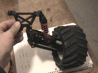
Mike devised a very simple and elegant strategy for connecting the Traxxas parts to the robot, as illustrated in the
following images.
The first step was to machine axles and bearing supports to provide the interface between the robot chassis and the
suspension and drive shafts.
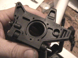
 The factory bulkheads have a round receiver that normally aligns the suspension with the differential.
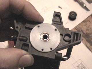
We machined nylon
bearing supports to fit the receiver and screwed them to the bulkheads.
The nylon parts have the interesting property that all screws are essentially "self-locking."
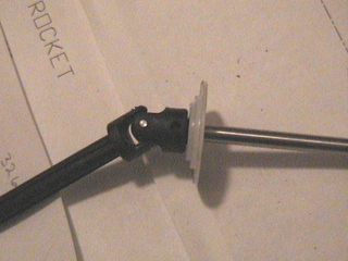
 We machined axles from 1/4" drill rod and milled the ends to mate with the driveshaft u-joints.
These support the outer ends of the timing belt pulleys that are used on jBot to drive the wheels.
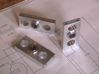
The inboard ends of the drive axles are supported by aluminium bearing struts, with a 12mm ball bearing inserted in each side.
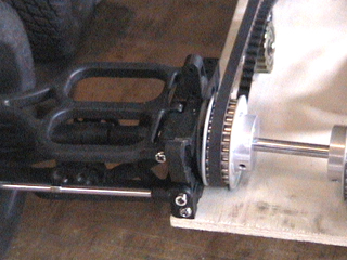
 Aluminium pulleys from Stock Drive Products are locked with set screws to flats machined on the axles. They
are driven by 5mm timing belts.
Aluminium pulleys from Stock Drive Products are locked with set screws to flats machined on the axles. They
are driven by 5mm timing belts.
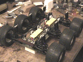
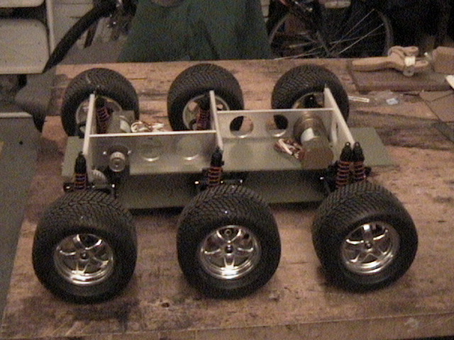
All three wheels on each side will be synchronously belt-driven by a single motor. The
components are shown here temporarily assembled on a styrofoam jig, with the yellow
battery packs already installed.
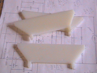 Three shock tower bulkheads were machined from nylon to mate with the E-MAXX suspension bulkheads.
These were later dyed chocolate brown using "RIT" dye from the grocery store, along with all the hand-made nylon parts.
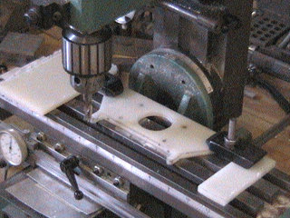
 Upper and lower chassis plates were machined from 1/8" structural fiberglass we ordered from
McMaster-Carr.
Upper and lower chassis plates were machined from 1/8" structural fiberglass we ordered from
McMaster-Carr.
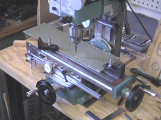
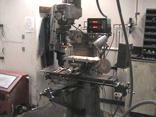
Some of the
mill work required a bigger mill.
Mark Sims and I
were able to get access to a nice Bridgeport vertical mill in the engineering department
at SMU (thanks Necdet!) for those operations.
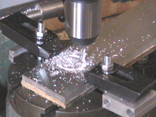
 Mounts for the gearhead motors were machined from 1/4" aluminium plate using
a rotary milling table belonging to fellow Denton robot builder Duane Gustavus,
Mounts for the gearhead motors were machined from 1/4" aluminium plate using
a rotary milling table belonging to fellow Denton robot builder Duane Gustavus,
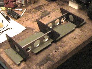
Here are the nylon shock tower bulkheads, the fiberglass upper chassis plate, and the
aluminium motor mounts, assembled.
Nylon ball-bearing idler pulleys were fabricated from
nylon barstock and 7/16" roller bearings, and adjustable idler supports were machined from 1/4"
aluminium plate.
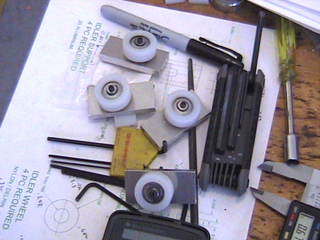 These are used to maintain tension on the timing belts that connect the
three wheels on either side of the robot.
These are used to maintain tension on the timing belts that connect the
three wheels on either side of the robot.
Mike insisted that we not use mere washers under the head of the hold-down screws, but
rather that we machine "buttons" from 3/4" octagonal stock, which I did. I must admit they look
pretty high-tech.
The idler pulleys are as large in diameter as we could make them, about 1.5", and still fit in the
available space. This reduces the amount of bending of the timing belt, which requires horsepower.

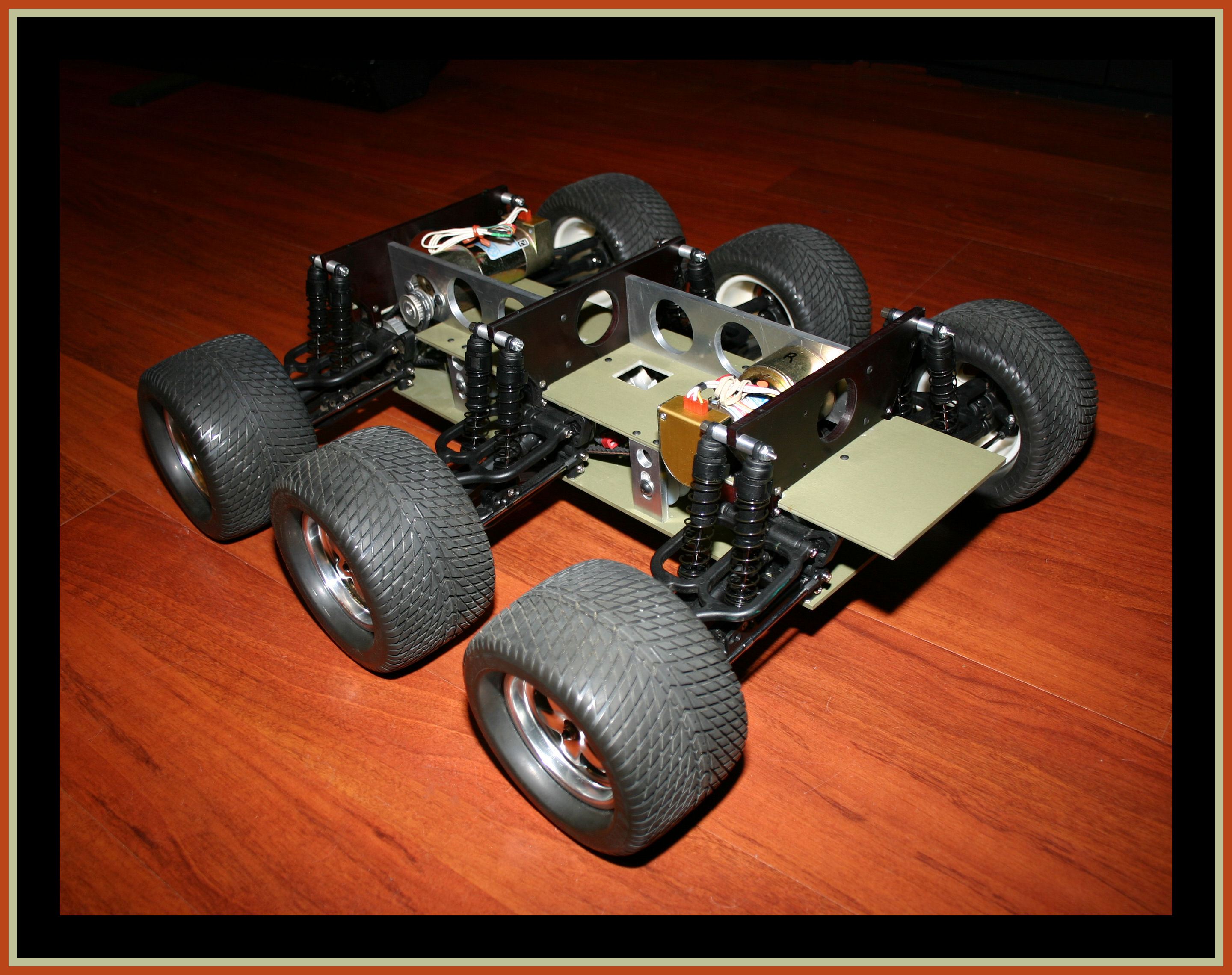
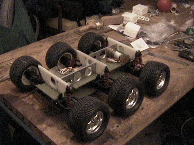
 Here is an early test fit of all of the upper and lower chassis components.
The drive components, pulleys, timing belts, idlers, and associated batteries are still
to be installed. (Note that the
nylon shock tower bulkheads are still white in these pictures.)

Here's a nice potrait of the assembled jBot chassis. It was taken by Dave Ellis on stage at the
Dallas Science Place April 2005 DPRG monthly meeting. This was before the electronics and sensors were installed on the platform.
Click on the image for a high-resolution version.
jBot April 2005
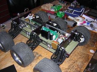
The mounting arrangement of a pair of
Devantech H-Bridge intelligent electronic speed controllers and the
MRM 68332 microcontroller on the vehicle chassis can be seen in
this image. The wiring harnesses (not shown
here) are fed through the interior of the platform. Click on the image for a larger version.
Click here for the jBot homepage, including videos of jBot in the Colorado Rockies.
(C) 2005-2011 David P. Anderson
last update:16 December 2011 dpa

 Here is an early test fit of all of the upper and lower chassis components.